Craftsman 21829 Operation Manual - Page 11
Height/bevel Adjusting Handwheel - Located - rip fence
 |
View all Craftsman 21829 manuals
Add to My Manuals
Save this manual to your list of manuals |
Page 11 highlights
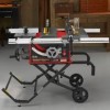
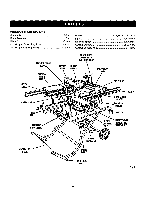
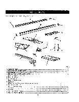
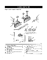
KNOW YOUR TABLE SAW See Figure 2. Before attempting to usethis product, familiarize yourself with air operatingfeatures and safety rules. ACCESSORY TABLE - The accessory table may be used on either the right or left side of the saw as needed and has been designedfor use with some reuters. A router mounted on the accessorytable wilrprovide expanded capabilities for making rabbets, grooves, chamfers,dovetails, and mortiseand tenon joints. ADJUSTING CLAMP - This clamp looksthe miter fence stthedesiredcuringangla. ALIGN-A-CUT INSERT - A plastic insert on which marks may be made to indicate the locationof the saw cut on the workplace. ANTI-KICKBACK PAWLS - Kickback is a hazard in which the workplace is thrown back toward the operator.The teeth on the anti-kickback pawls point away _om the workpiece. If the workpiecs should be putisd back toward the operator, the teeth dlg intothe wood to help prevent or reduce the possibility of kickback. BEVEL SCALE - The easy-to-raad scale on the frontof the cabinet shows the exact blade angle. BLADE - This saw is provided with a 36-tooth, 10 in. carbidebladeT.he blade is raised and lowered with the height adlusting handwheeLBevel angles are lockedwith the bevel lockinglever. A WARNING: Do not use blades rated _easthan the speed of this tool. Failureto heed this warning could resultin personalinjury. BLADE GUARD - Always keep the blade guard down over the saw blade for through-sawing cuts. BEVEL LOCKING LEVER -This lever, placed just under the saw table surface on the frontof the cabinet, {coke the angle setting of the blade. HEIGHT/BEVEL ADJUSTING HANDWHEEL - Located on the front of the cabinet, use this handwheal to lower and raise the blade for height adjustmentsor blase replacement. This f_ndwhea( also makes the adjustment for bevel ang[as easy. LEG STAND - Attached to the table saw base, the leg stand opens and closes with ease. MITER FENCE- The fence attaches to the slidingmiter table and can be angled for miter and compound miter cuts as wall as straight cuts such as cross, bevel cross, rip, and bevel rip cuts. MITER GAUGE - The miter gaugealigns the wood for a cross cut. The easy-to-read indicatorshows the exact angle for a miter cut, with positivestops at 90° and 45 °. MITER GAUGE GROOVES - The miter gauge rides in the grooves on the accessory table. MOTOR - The powerful inductionmotor,with capacitor start and V-belt drive, is housed in a sturdysteel base. RA]L_ - Front end rear railsprovide support for large workpiecas and the rip fence. RIP FENCE - A sturdy metal fence guidesthe workplace and is securedwith the locking handle.Grooves runalong the top and sides of the rip fence for use with optional clamps and accessories. RIVING KNIFE/SPREADER - A metal piece of the blade guard assembly, slightly thinner than the saw blade, which helps keep the ked open and prevent kickback. SCALE - Located on the front rail, the easy-to-readst;ale provides precisemeasurements for dp cuts. SLIDING MITER TABLE - The miter table slideseasily along the miter table base ailowlng the operator to move the warkpiece across the saw table. SWITCH/_SEMBLY - This saw has an easy access powar switch located below the front rm_.To lock the switch in the OFF position,remove the switch keyfrom the sw_tch.Place the key in e location that is inaccessible to children and others not qualifiedto use the tool 11
-
 1
1 -
2
-
3
-
4
-
5
-
 6
6 -
 7
7 -
 8
8 -
 9
9 -
 10
10 -
 11
11 -
 12
12 -
 13
13 -
 14
14 -
 15
15 -
 16
16 -
17
-
18
-
19
-
20
-
21
-
22
-
23
-
24
-
25
-
26
-
27
-
28
-
29
-
30
-
31
-
32
-
33
-
34
-
35
-
36
-
37
-
38
-
39
-
40
-
41
-
42
-
43
-
44
-
45
-
46
-
47
-
48
-
49
-
50
-
51
-
52
-
53
-
54
-
55
-
56
-
57
-
58
 |
 |
