Craftsman 21829 Operation Manual - Page 30
Adjusfrnenf making, right - table saw manual
 |
View all Craftsman 21829 manuals
Add to My Manuals
Save this manual to your list of manuals |
Page 30 highlights
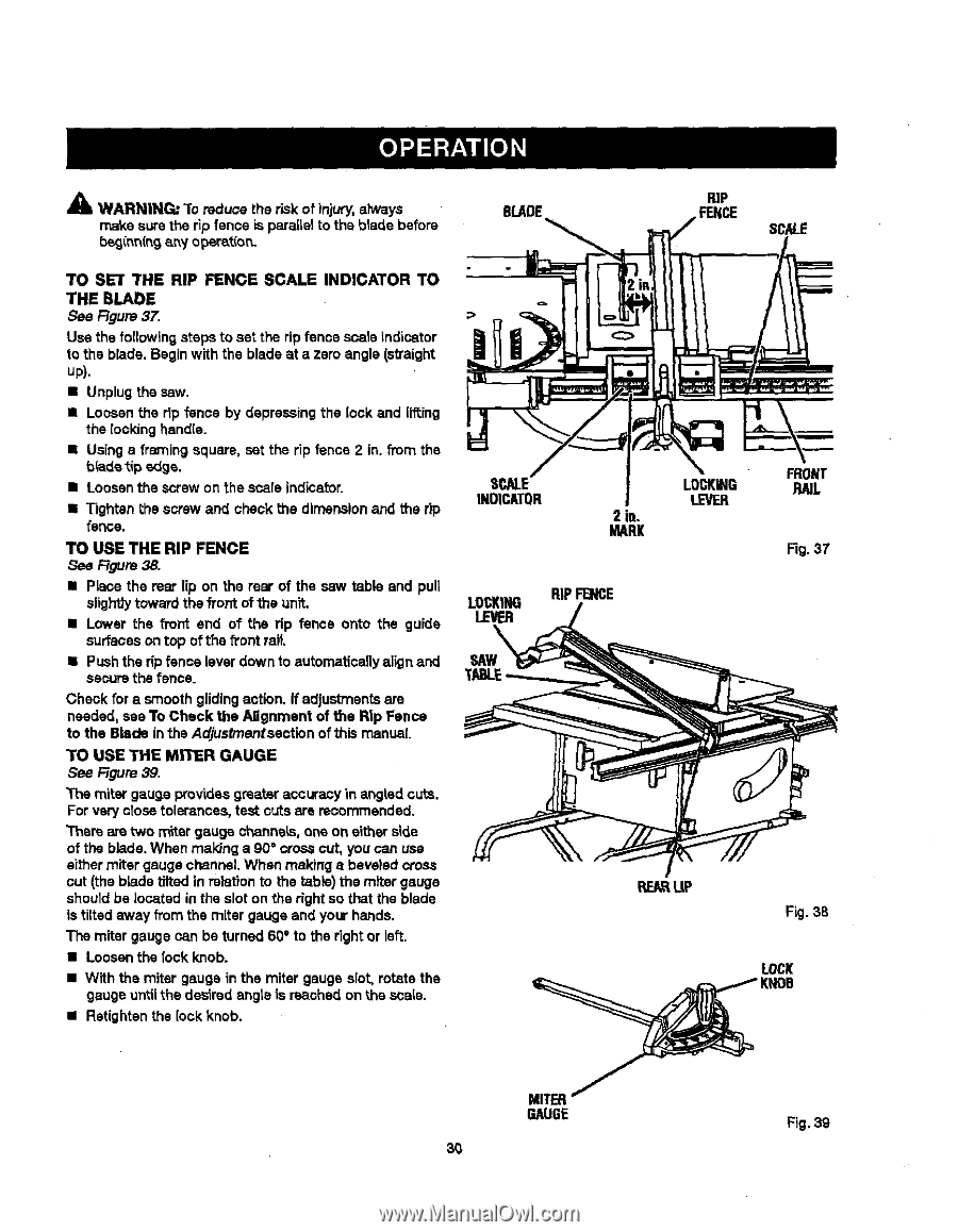
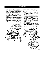
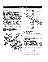
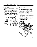
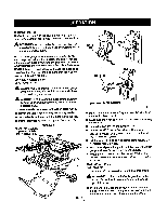
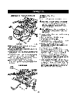
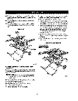
& WARNING: "1"roeduce the r_k of injury, always make sure the rip fence is parallel to the b_ade before b_innfng any opar_t'_o_. BLADE RiP FENCE SCALE TO SET THE RIP FENCE SCALE INDICATOR TO THE BLADE See Figure 37. Use the following steps to set the rip fence scale indicator to the blade. Begin with the blade at a zero angle (sVaight up). • Unplugthesaw. • Loosen the rip fence by depressing the lock and lifting the rooking handle. • Using s framing square, set the rip fence 2 in. from the bride tipedge. • Loosen the screw on the scale indicator. • Tighten the screw and check the dimension and the rip fence. TO USE THE RIP FENCE Figure 38. • Place the mar lip on the rear of the saw table and pull slighttytoward the front of the unit. • Lower the front end of the rip fence onto the guide surfaces on top ofthe front rail. • Push the rip fence lever down to automaticaflyalign and secure the fence. Cheek for a smooth glidingaction. If adjustmentsare needed, see To Check the Alignment of the Rip Fence to the Blade in the Adjusfrnenfsection of this manual. TO USE THE MITER GAUGE See F=Jgur3e9. The miter gauge providesgreater accuracy in angHd cuts. For very close tolerances, test cuts are recommended. Them are two miter gauge channels, one on either side of the blade. When maldng a 90 ° cross cut, you can use either miter gauge channel. When making a beveled cross cut (the blade tilted in relationto the table) the miter gauge sheutd be located in the slot on the right so that the blade is tilted away from the miter gauge and your hands. The miter gauge can be turned 60 ° to the right or left. • Loosen the lock knob. • With the miter gauge in the miter gauge slot, rotate the gauge until the desired angte is reached on the scale. • Retighten the lock knob. E INDICATOR 2 in. MARl( LOCKING LEVER RA]L Fig. 37 LOCKING RiP FENCE LEVER SAW RE_ L|P Fig. 38 LOCK MITER GAUGE Fig. 39
-
 1
1 -
2
-
3
-
4
-
5
-
6
-
7
-
8
-
9
-
10
-
11
-
12
-
13
-
14
-
15
-
16
-
17
-
18
-
19
-
20
-
21
-
22
-
23
-
24
-
 25
25 -
 26
26 -
 27
27 -
 28
28 -
 29
29 -
 30
30 -
 31
31 -
 32
32 -
 33
33 -
 34
34 -
 35
35 -
36
-
37
-
38
-
39
-
40
-
41
-
42
-
43
-
44
-
45
-
46
-
47
-
48
-
49
-
50
-
51
-
52
-
53
-
54
-
55
-
56
-
57
-
58
 |
 |