Craftsman 21829 Operation Manual - Page 28
see To Check Miter Base Parsltellm'n.
 |
View all Craftsman 21829 manuals
Add to My Manuals
Save this manual to your list of manuals |
Page 28 highlights
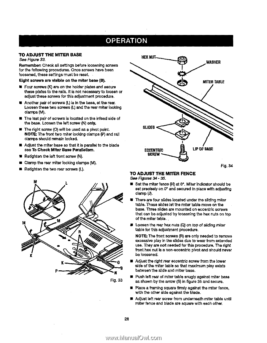
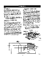
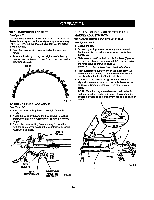
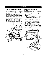
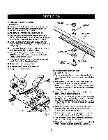
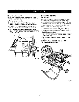
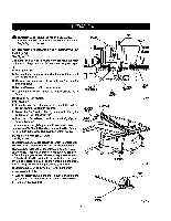
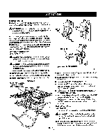
TO ADJUST THE MITER BASE See Figure 33. Remember: Check all settings before looseningscrews for the foflowfng procedures.Once screws have bean toosened, these settingsmust be reset. Eight screws ere visible on the miter base (B). • Four screws (k")o_eon the holderplates and secure these plates to the rails. It is not necessaryto loosen or adjust these screws for this adjustment procedure. • Another pair of screws (L)is in the base, at the rear. Loosen these two screws(I-) end the rear miter (ocking o[amps (M). • The last paZrof screws is located on the infesdside of the base. Loosen the left screw (N) only, • The right screw (O) will be used as a pivot point. NOTE: The fTonttWOmiter locking c(amps (P) and rail clarnps shouldrem_n locked. • Adjust the miter base so that it is parallelto the blade see To Check Miter Base Parsltellm'n. • Retighten the [eft fi'ont screw (N). • Clamp the rear miter Locking clamps (M). • Retighten the two rear screws (L). M L M K K Fig. 33 MITERTABLE SLIDES Fig. 34 TO ADJUST THE MITER FENCE See F_Jras 34 - 35. II Set the miter fence (H) at 0°. Miter indicatorshould be set preciselyon 0° and secured in place with adjusting cl_¢np(J). • Ther_ are four slideslocated under the s_dingmiter tab, le. These slideslet the miter table move on the base. Three slidesare mounted on eccentricscrews that can be adjusted by looseningthe hex nuts on top of the miter table., • Loosen the rear hex nuts (Q) on top of slidingmiter table for this adjustment procadure. NOTE: The front screws (R)are onty needed to remove excessive play in the slides due to wear from extended use. They are not neededfor this procedure.The right front hex nut is a non-eocantricpivot and should never be ;oasened. • Adjust the right rear eccantrJcscrew from the lower side of the miter table so that maximum play exists betweenthes_ideand m'ftarbase. • Push left rear of miter table snugly against miter base as shown by the arrow (S) in figure 35 and secure, • P_ca a fi_'nlng square firmlyagainst the miter fence, with the other ,ride againstthe blade. • Adjust left rear screw from undern_th miter table until miter fence end brads are square with each other, 28
-
 1
1 -
2
-
3
-
4
-
5
-
6
-
7
-
8
-
9
-
10
-
11
-
12
-
13
-
14
-
15
-
16
-
17
-
18
-
19
-
20
-
21
-
22
-
 23
23 -
 24
24 -
 25
25 -
 26
26 -
 27
27 -
 28
28 -
 29
29 -
 30
30 -
 31
31 -
 32
32 -
 33
33 -
34
-
35
-
36
-
37
-
38
-
39
-
40
-
41
-
42
-
43
-
44
-
45
-
46
-
47
-
48
-
49
-
50
-
51
-
52
-
53
-
54
-
55
-
56
-
57
-
58
 |
 |