Craftsman 21829 Operation Manual - Page 26
Tochangethebladedepth
 |
View all Craftsman 21829 manuals
Add to My Manuals
Save this manual to your list of manuals |
Page 26 highlights
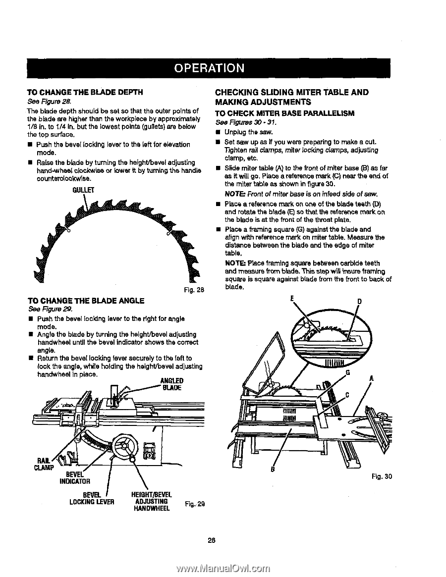
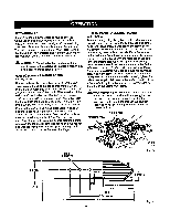
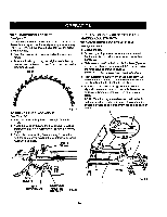
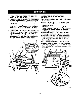
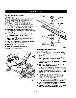
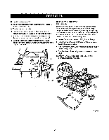
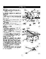
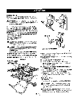
TOCHANGETHEBLADEDEPTH See Rgure 28. The blade depth should be set so that the outer points of the blade are higherthan the workpisce by approximately 1/8 in. to 1/4 in. but the lowest points (gullets)are below the top surface. • Push the bevel locking [everto the left for elevation mode. • Raise the blade byturning the height/beveladjusting hand-whes, [ ck>ck'wissor !ower it by turning the hendLs oo_nterdo_k'w_se. QULLL='( Fig. 28 TO CHANGE THE BLADE ANGLE See Figure 29. • Push the bevel [ocVdnglever to the right for angle mode. • Angle the blade by turning the height/beveladjusting handwheal until the bevel indicator shows the correct angle. • Return the bevel locking lever securelyto the (eft to lock the angle, whirs holdingthe height/beveladjusting handwheal in piece. AN_I.ED CHECKING SLIDING MITER TABLE AND MAKING ADJUSTMENTS TO CHECK MITER BASE PARALLELISM See Figures 30 - 31. • Unplug the saw. • Set saw up as if you were preparing to make a out. Tighten railclamps, miter lockingclamps, adjusting clamp, etc. • Slide miter table CA)to the frontof miter base _) as far as it will go, Place a reference mark (C) near the end of the miter _abteas shown in figure30. NOT_ Front of miter base is on infead s'_e of saw. • Place a reference mark on one of the b_ds teeth (D) and rotsta the blade (1_so that the referencemark on the blade is at the front of the throat plate. • Place a framing square (G) againstthe blade and alignwith referencemark on miter fable. Measure the distance between the blade end the edge of miter table. NOTE: Place framing square between carbide teeth and measure fro_ b_ade.Th_s stepw_ _nsurefTan_ng squareissquareagainstbladefromthsfronto back of blade, E 0 A INDICATOR BEVEL LOCKINGIFVER HEIgHT/BEVEL ADJUSTING Fig,.2g HANDWHEEL 26 Fig. 30
-
 1
1 -
2
-
3
-
4
-
5
-
6
-
7
-
8
-
9
-
10
-
11
-
12
-
13
-
14
-
15
-
16
-
17
-
18
-
19
-
20
-
 21
21 -
 22
22 -
 23
23 -
 24
24 -
 25
25 -
 26
26 -
 27
27 -
 28
28 -
 29
29 -
 30
30 -
 31
31 -
32
-
33
-
34
-
35
-
36
-
37
-
38
-
39
-
40
-
41
-
42
-
43
-
44
-
45
-
46
-
47
-
48
-
49
-
50
-
51
-
52
-
53
-
54
-
55
-
56
-
57
-
58
 |
 |