Craftsman 21829 Operation Manual - Page 21
See Flours21., assembly, Opera#on, See Operation
 |
View all Craftsman 21829 manuals
Add to My Manuals
Save this manual to your list of manuals |
Page 21 highlights
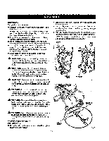
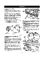
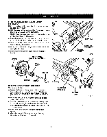
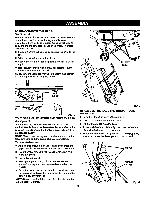
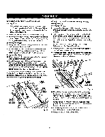
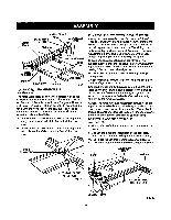
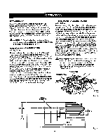
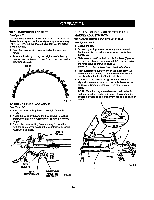
I!_STIIIG CI_INI,[P TO CHECK SL|D|NG M_'ER TABLE ASSEMB!3/' MITER FENCE \ MITERFENCE KNOB HOLDER ,HOLE"A" ATI'ACHMEN'T The square relationshipbetween the blade and the miter BOLT fence as it travels the entire distancefrom the frontto the rear of the miter table base duringa cut is very important for m_ng preciseand accurate cuts.The slidingmiter table assembly has been preset at the factory. However, misallgnment during shippingor requirementsfor very LOCATORPiN precise and accurate cuts may requirerce[ignment. To avoid unnecessarysetups arid ad.iuatmentsw, e suggest that you check these setups carefullywith a fram- ing square and make practicecuts in scrap wood before making finishcuts in good workpisces. INDICATOR HOLE=B" QUICKSTOP HOLE"C" TABLESLOT Fig. 20 TO LOCK SLIDING MITER TABLE See Flours21. The miter table elides allowing the operatorto elide the workplsce across the saw, A miter slide lock is mounted on the front of the miter table to lock it in place. The miter slide lock is placed in a slot on the base to align the miter tabla with the h'ont edge of the saw table. The sliding miter table shouldbe locked for any cut in which the operator prefersa fixed table. • To lock the miter table with the base projectingto the front, place miter slide lock in the back slot on the base. • To lock the miter table with the base projectingto the back, place miter slide lock in the front slot on the base. NOTE: Followthe general rule of measuring twice and cuttinognce. Do not loosen any screws. Once screws have been loosened, settings must be reset. Two basic checks should be made before using the miter table"(1) the miter base must be parallelto the blade as the table slides fTomthe front to back, and (2) the miter fence must be squareto the blade when set at exactly zero (0") on the rafter table scats. NOT_ The miter tablehas adjus_ant screws for squaring miter fence tc blade and maintaining0 ° scale settings when miter base adjustments are rsc,uired.These checks and adjus't_entsare exp_ined in step-by-step procedures in the Opera#on sectionend depend on each other. TO INSTALL ACCESSORY TABLE See Figure22. • Fit the tabs on the back of the accessory table into the rear rail. • Posi_onthe slot on the undersideof the accesaory table ontothe frontrail and tighten the lever securely. NOTE: To use the optional routeraccessories included with this product, refer to the Operationsectionfor usage. MITER SLIDELOCK TO LOCK ACDESSORY TABLE REARRNL SLOT8FORLOCKING MITERTABLE Fig. 21 \ TO UNLOCK LEVER 21 FITUP OFT_BL,E IKTOREARRAIL Fig. 22
-
 1
1 -
2
-
3
-
4
-
5
-
6
-
7
-
8
-
9
-
10
-
11
-
12
-
13
-
14
-
15
-
 16
16 -
 17
17 -
 18
18 -
 19
19 -
 20
20 -
 21
21 -
 22
22 -
 23
23 -
 24
24 -
 25
25 -
 26
26 -
27
-
28
-
29
-
30
-
31
-
32
-
33
-
34
-
35
-
36
-
37
-
38
-
39
-
40
-
41
-
42
-
43
-
44
-
45
-
46
-
47
-
48
-
49
-
50
-
51
-
52
-
53
-
54
-
55
-
56
-
57
-
58
 |
 |
