Craftsman 21829 Operation Manual - Page 43
Tocheckthealignmentoftheripfence, Totheblade
 |
View all Craftsman 21829 manuals
Add to My Manuals
Save this manual to your list of manuals |
Page 43 highlights
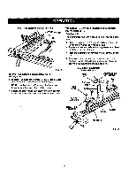
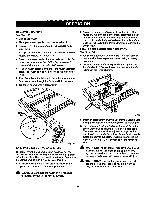
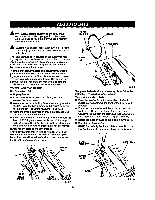
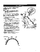
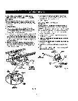
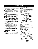
TO CHECKTHEALIGNMENTOFTHERIPFENCE TOTHEBLADE SeeFigure 64. • UnpLugthe saw. • Raise the (ooking handle to permitthe rip fence to be moved. BLADE TO ADJUST THE BEVEL LOCKING LEVER See FTgura65. "Fhebevel looking levermay work loose and require adjusting. To adjust: • Unplug the saw. • Push the lever full left to the fecked position. • Remove the screw on t_e heighS_bevealdjusting handwhaeLYouwritneed the 3/16 in, hex key for this procedure. • Remove the height/bevel adjusting handwhseland cam. Pullout the cam. • Remove the set screw on the bevel lockinglever. • Remove the bevel lockinglever from hex nut, II Relocate bevel locking lever on the hsx nut. • Replace set screw and tighten securely. • Replace the cam so that the lobe is againstthe tab. Make sure the cam is seated in the lever. • Reaseemb)sthe height/bevel adjusting handwheelto the shaft and cam. Checkwhether the lever is now in the desired position.Tightenscrew securely. HEIGHT/BEVEALDJUSTING HANOWHEEL SCREWS SOCKET H_DS_EW SETSCREW LOCKING HANDLE Fig. 64 • Place a framing square beside the blade and move the rLpfence up to the square. Take the dimensionon the rip scale. • Move the fence back and turn the framing square180 ° to check the other aide. • If the two dimensionsare not the same, loosenthe two s_'ewa on _s fence end align it. • Retightenthe two screws. • Make two or three test cuts on scrap wood. it the cuts are not true, repeat the process. NOTE: The rip fence must be secure when the locking handle is engaged. The clamp screwon the rear of the rip fence istightened by turning clockwiseto increasetightnessof the rear of the rip fence. CAM COMPRESSION SPRING HANDWHEEL ADAPTER 43 HEXNUT , BEVEL LOCKING LEVER Fig. 65
-
 1
1 -
2
-
3
-
4
-
5
-
6
-
7
-
8
-
9
-
10
-
11
-
12
-
13
-
14
-
15
-
16
-
17
-
18
-
19
-
20
-
21
-
22
-
23
-
24
-
25
-
26
-
27
-
28
-
29
-
30
-
31
-
32
-
33
-
34
-
35
-
36
-
37
-
 38
38 -
 39
39 -
 40
40 -
 41
41 -
 42
42 -
 43
43 -
 44
44 -
 45
45 -
 46
46 -
 47
47 -
 48
48 -
49
-
50
-
51
-
52
-
53
-
54
-
55
-
56
-
57
-
58
 |
 |
