Craftsman 21829 Operation Manual - Page 44
Toaugnthemiterlockingclamps - replacement parts
 |
View all Craftsman 21829 manuals
Add to My Manuals
Save this manual to your list of manuals |
Page 44 highlights
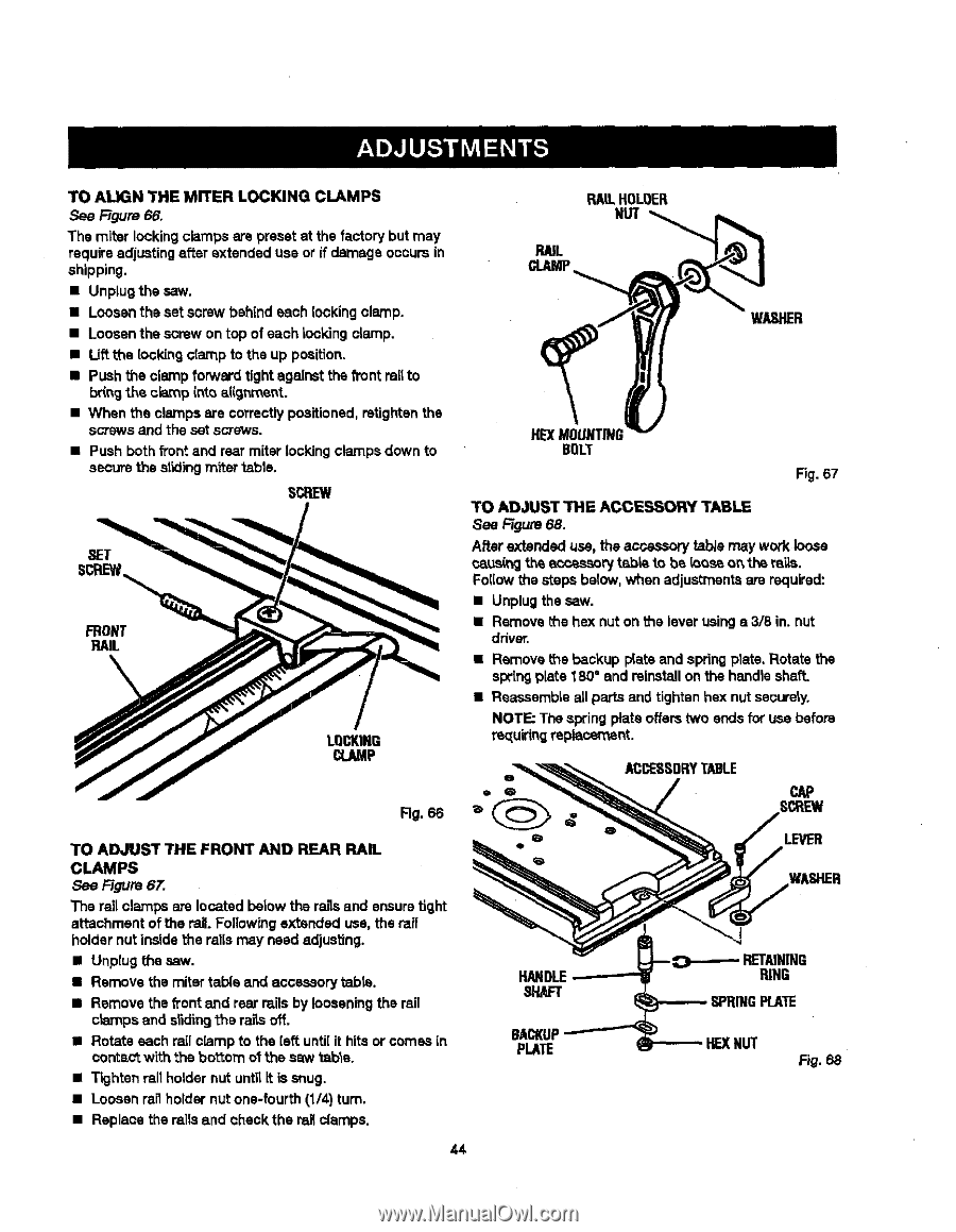
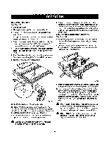
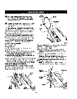
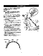
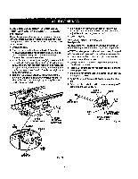
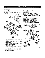
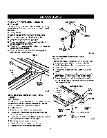
TOAUGNTHEMITERLOCKINGCLAMPS See Figure 66. The miter locking clamps are preset at the factory but may requireadjustingafter extended use or if damage occursin shipping. • Unplug the saw. • Loosen the set screw behind each lockingclamp. • Loosen the screw on top of each Iockingclamp. • Uft the locldng clamp to the up position, • Push the clamp forward tight against the front railto bringthe c_p into aiigr_'_ent. • When the clamps are correctlypositioned, retightenthe scows and the set screws. • Push both front and rear miter lockingclamps down to secure the s|idingmiter table. SCREW RAILHOLOER NUT RAIL CLAMP WASHER HE)(MOUNTING BOLT Fig. 67 TO ADJUST THE ACCESSORY TABLE See Rgure 68. After extended use, the acce..-_, tab/e may work loose caus(_ th_ accessory table to be {oos_ o_ the ra'_s. Foi(ow the steps below, when adjustmentsare required: • Unplug the saw. • Remove the hex nut on the lever using s 3/8 in. nut driver. • Remove t_e backup p{ateand spring plate. Rotate the springplate 180° and reinstallon the handle shaft. • Reassemble all parts end tighten hex nut securely. NOTE; The spring plate offers two ends for use before re_[uiringreplacement. ACCESSORTYABLE Fig. 66 TO ADJUST THE FRONT AND REAR RAIL CLAMPS See Rgure 67. The rail cramps ate located below the raUsand ensure tight attachment of the rail. Followrngextended use, the rail holder nut inside the rails may need adjusting. • Unplug the saw. • Remove the miter table and accessory tabla. • Remove the _ont emdrear rails by looseningthe rail crampsand dlding the rai_soff. • Rotate each rail clamp to the {sft unti{it hits or comes in correct with the bo'_om ot the saw table. • Tighten rait holder nut until it is snug. • Loosen rail holder nut one-fourth (1/4) turn. • Replace the rails and check the rail clamps. 44 HAl _"IAFT BACKUP PLATE LEVER RING SPRINGPLATE HEXNUT F_.68
-
 1
1 -
2
-
3
-
4
-
5
-
6
-
7
-
8
-
9
-
10
-
11
-
12
-
13
-
14
-
15
-
16
-
17
-
18
-
19
-
20
-
21
-
22
-
23
-
24
-
25
-
26
-
27
-
28
-
29
-
30
-
31
-
32
-
33
-
34
-
35
-
36
-
37
-
38
-
 39
39 -
 40
40 -
 41
41 -
 42
42 -
 43
43 -
 44
44 -
 45
45 -
 46
46 -
 47
47 -
 48
48 -
 49
49 -
50
-
51
-
52
-
53
-
54
-
55
-
56
-
57
-
58
 |
 |