Craftsman 21829 Operation Manual - Page 41
Tocheck,replace, Oradjusttheriving, Knifeandbladeguardassembly
 |
View all Craftsman 21829 manuals
Add to My Manuals
Save this manual to your list of manuals |
Page 41 highlights
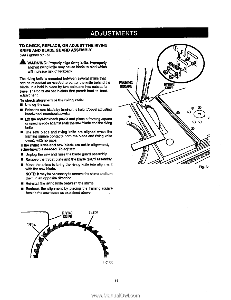
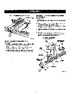
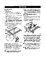
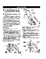
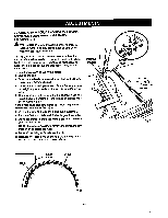
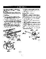
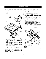
TO CHECK,REPLACEO, RADJUSTTHERIVING KNIFEANDBLADEGUARDASSEMBLY See Figures 60 - 61. A AlL WARNING: Propertyalign riving knits. |mproperiy atigned rivingknife may cause blade to btndwhich will increaserisk of kickback. The rivingknife is mounted between several shims that can be relocated as needed to center the knife behind the blade. It is held in place by two bolts and hex nutsat its base. The bolts are set in slots that permit front-to-back adjusb'nent. "Tocheck a_gnment of the _vin 9 knife: • Unplug the saw. • Raisethe saw blade byturningthe height/beveladiuating har_twheel¢ountsml_ckwisa. • Lift the anti-kickback pawls and place a framing square or s'_mighet dge againstboththe saw bladeand the riving knife. • The saw blade and riving knife are aligned when the framing square contacts both the biade and rh/ingknife eventy with no gaps. If the dvthg knife and saw blade am not In alignment, adjustment is needed. To adjust:. • Unplug the saw and raise the b_adeguard assambly. • Remove the throat plate and the blade guard assembly. • Move the shims to bring the riving knife into alignment with the saw blade. NOTE"It may be necessaryto removethe shimsand turn them in an opposite direction. • Ralnstaflthe rivingknife between the shims. • Recheck the atignment by placing the framing square beside the saw blade as explained above. FRAMING SQUARE 1/8 in. RIVING KNIFE BLADE R_. 60 41 Fig. 61
-
 1
1 -
2
-
3
-
4
-
5
-
6
-
7
-
8
-
9
-
10
-
11
-
12
-
13
-
14
-
15
-
16
-
17
-
18
-
19
-
20
-
21
-
22
-
23
-
24
-
25
-
26
-
27
-
28
-
29
-
30
-
31
-
32
-
33
-
34
-
35
-
 36
36 -
 37
37 -
 38
38 -
 39
39 -
 40
40 -
 41
41 -
 42
42 -
 43
43 -
 44
44 -
 45
45 -
 46
46 -
47
-
48
-
49
-
50
-
51
-
52
-
53
-
54
-
55
-
56
-
57
-
58
 |
 |