Craftsman 21829 Operation Manual - Page 42
TO SET THE B_VEL - extension
 |
View all Craftsman 21829 manuals
Add to My Manuals
Save this manual to your list of manuals |
Page 42 highlights
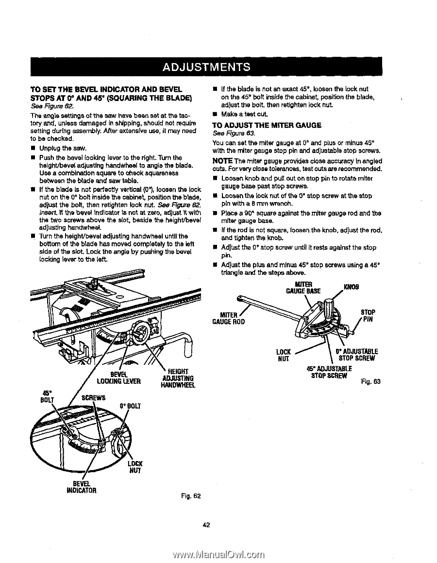
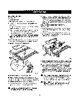
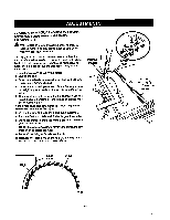
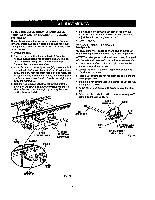
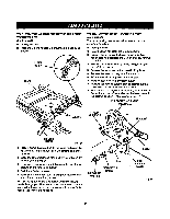
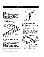
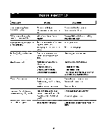
TO SET THE B_VEL INDICATOR AND BEVEL STOPS AT 0_ AND 45 ° (SQUARING THE BLADE) Figure 62. The angle sa_mgs oFthe saw have been set at the _actory and, unlessdamaged in shipping, should not require setting during assembly. After extensive use, it may need to be checked. • Unplug the saw. • Push the bevel looking lever to the right.Turn the t_eight/beve{ adjusting handwhsel to angle L'heblade. Use • combinationsquare to check squareness between the blade and saw table. • If the blade is not perfectly vertical (0_),loosen the lock nut on the 0° bolt _nside the cabinet, positionthe blade, adjust the bolt, then retighten lock nut. See Figure 62, insall, if the banal indicator is not at zero, adjust_tw_.h the "twoscrews above the slot, beside the heighVbevel adjusting handwheel. • Turn the heighVbevel adjusting ha.ndwhesluntilthe bottom of the blade has moved completelyto the left side of the slot. Lock the angle by pushing the bevel _ocking lever to the left. • If the blade is not an exact 45 °, loosenthe lock nut on the 45° bolt inside the cabinet, positionthe blade, adjust the bolt, then retighten lock nut. • Make a test cut. TO ADJUST THE MITER GAUGE See Figure 63. You can set the miter gauge at O° and plus or minus 45° with the miter gauge stop pin and adjustablestop screws. NOTE The miter gauge providesclose accuracy in angled cuts. Forvery close tolerances,test cutsare recommended. • Loosen knob and pull out on stop pin to rotate miter gauge base paststop screws. • Loosenthe lock n_t of the 0 ° stop screw st the stop pinwith a 8 rnm wrench. • Place a 90" squareagainstthe m_ar gauge rod and the miter gauge base. • If the rod is not square, loosenthe knob, adjust the rod, and tighten the knob. • Adjust the 0 ° atop screw until it restsagainst the stop pin. • Adjust the plus end minus 45° stop screws usinga 45 ° triangle and the stepsabove. MITER GAUGEBASE m MITER_ BOLT GAUGEROD BEVEL LOCKINGLEVEE[ ADHJEUIGSHTITNG HANDWHEEL O"BOLT LOCK/ NUT O"ADJUSTABLE STOPSCREW 45"ADJUSTABLE STOPSCREW Fig. 63 BEVEL INDICATOR LOCK NUT Fig. 62 42
-
 1
1 -
2
-
3
-
4
-
5
-
6
-
7
-
8
-
9
-
10
-
11
-
12
-
13
-
14
-
15
-
16
-
17
-
18
-
19
-
20
-
21
-
22
-
23
-
24
-
25
-
26
-
27
-
28
-
29
-
30
-
31
-
32
-
33
-
34
-
35
-
36
-
 37
37 -
 38
38 -
 39
39 -
 40
40 -
 41
41 -
 42
42 -
 43
43 -
 44
44 -
 45
45 -
 46
46 -
 47
47 -
48
-
49
-
50
-
51
-
52
-
53
-
54
-
55
-
56
-
57
-
58
 |
 |