Dell Inspiron One 2205 Service Manual - Page 14
Replacing the Mini-Cards
 |
View all Dell Inspiron One 2205 manuals
Add to My Manuals
Save this manual to your list of manuals |
Page 14 highlights
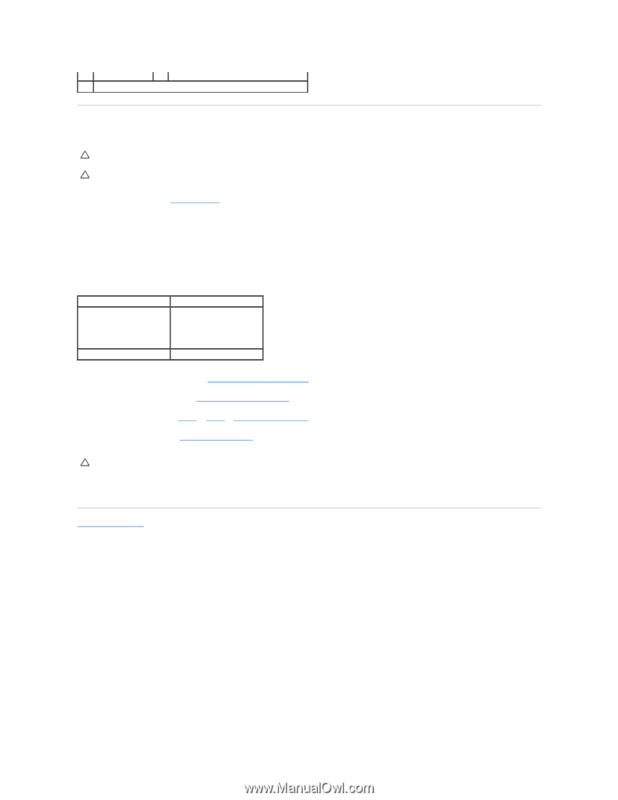
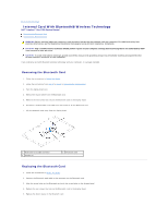
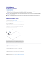
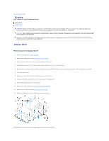
1 Mini-Card 3 screws (2) 2 system board connector Replacing the Mini-Card(s) CAUTION: The connectors are keyed to ensure correct insertion. Use of excessive force may damage the connectors. CAUTION: To avoid damage to the Mini-Card, ensure that there are no cables or antenna cables under the Mini-Card. 1. Follow the instructions in Before You Begin. 2. Align the notch on the Mini-Card with the tab in the system-board connector. 3. Insert the Mini-Card at a 45-degree angle into the system-board connector. 4. Press the other end of the Mini-Card down and replace the two screws that secure the Mini-Card to the system-board connector. 5. Connect the appropriate antenna cable(s) to the Mini-Card you are installing. The following table provides the antenna cable color scheme for the Mini- Card(s) supported by your computer. Connectors on the Mini-Card Antenna Cable Color Scheme WLAN (2 antenna cables) Main WLAN (white triangle) white Auxiliary WLAN (black triangle) black TV tuner (1 antenna cable) black 6. Replace the system-board shield (see Replacing the System-Board Shield). 7. Replace the rear stand cover (see Replacing the Rear Stand Cover). 8. Follow the instructions from step 4 to step 7 in Replacing the Front Stand. 9. Replace the back cover (see Replacing the Back Cover). CAUTION: Before turning on the computer, replace all screws and ensure that no stray screws remain inside the computer. Failure to do so may result in damage to the computer. 10. Connect your computer and all attached devices to electrical outlets, and turn them on. Back to Contents Page
-
 1
1 -
2
-
3
-
4
-
5
-
6
-
7
-
8
-
 9
9 -
 10
10 -
 11
11 -
 12
12 -
 13
13 -
 14
14 -
 15
15 -
 16
16 -
 17
17 -
 18
18 -
 19
19 -
20
-
21
-
22
-
23
-
24
-
25
-
26
-
27
-
28
-
29
-
30
-
31
-
32
-
33
-
34
-
35
-
36
-
37
-
38
-
39
-
40
-
41
-
42
-
43
-
44
-
45
-
46
-
47
-
48
-
49
-
50
-
51
-
52
-
53
-
54
-
55
-
56
-
57
-
58
-
59
-
60
-
61
-
62
-
63
-
64
-
65
-
66
-
67
-
68
-
69
-
70
-
71
-
72
-
73
-
74
 |
 |