Dell Inspiron One 2205 Service Manual - Page 61
Replacing the System Board, Entering the Service Tag in the BIOS - driver
 |
View all Dell Inspiron One 2205 manuals
Add to My Manuals
Save this manual to your list of manuals |
Page 61 highlights
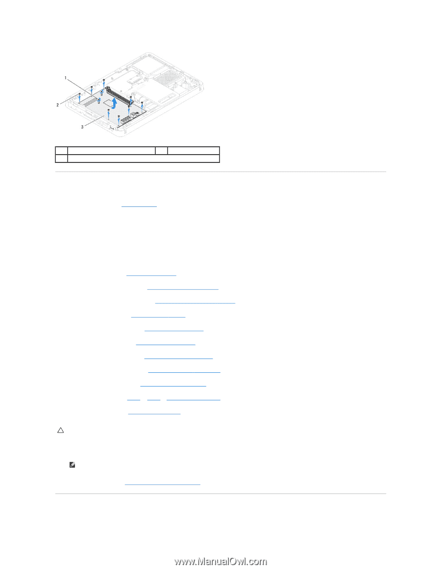
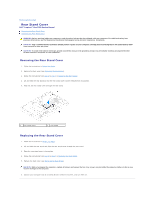
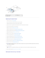
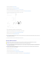
1 hex nut screws (2) 3 system board 2 screws (8) Replacing the System Board 1. Follow the instructions in Before You Begin. 2. Align the connectors on the system board with the slots on the chassis. 3. Replace the eight screws that secure the system board to the chassis. 4. Using a hex nut driver, replace the two hex nut screws that secure the system board to the chassis. 5. Connect all the required cables to the system board. 6. Replace the processor (see Replacing the Processor). 7. Replace the processor heat-sink (see Replacing the Processor Heat-Sink). 8. Replace the processor heat-sink fan (see Replacing the Processor Heat-Sink Fan). 9. Replace the Mini-Card(s) (see Replacing the Mini-Card(s)). 10. Replace the memory module(s) (see Replacing Memory Module(s)). 11. Replace the MXM assembly (see Replacing the MXM Assembly). 12. Replace the MXM-assembly fan (see Replacing the MXM-Assembly Fan). 13. Replace the system-board shield (see Replacing the System-Board Shield). 14. Replace the rear stand cover (see Replacing the Rear Stand Cover). 15. Follow the instructions from step 4 to step 7 in Replacing the Front Stand. 16. Replace the back cover (see Replacing the Back Cover). CAUTION: Before turning on the computer, replace all screws and ensure that no stray screws remain inside the computer. Failure to do so may result in damage to the computer. 17. Turn on the computer. NOTE: After you have replaced the system board, enter the computer's Service Tag into the BIOS of the replacement system board. 18. Enter the Service Tag (see Entering the Service Tag in the BIOS). Entering the Service Tag in the BIOS
-
 1
1 -
2
-
3
-
4
-
5
-
6
-
7
-
8
-
9
-
10
-
11
-
12
-
13
-
14
-
15
-
16
-
17
-
18
-
19
-
20
-
21
-
22
-
23
-
24
-
25
-
26
-
27
-
28
-
29
-
30
-
31
-
32
-
33
-
34
-
35
-
36
-
37
-
38
-
39
-
40
-
41
-
42
-
43
-
44
-
45
-
46
-
47
-
48
-
49
-
50
-
51
-
52
-
53
-
54
-
55
-
 56
56 -
 57
57 -
 58
58 -
 59
59 -
 60
60 -
 61
61 -
 62
62 -
 63
63 -
 64
64 -
 65
65 -
 66
66 -
67
-
68
-
69
-
70
-
71
-
72
-
73
-
74
 |
 |