Dell Inspiron One 2205 Service Manual - Page 60
System Board - memory
 |
View all Dell Inspiron One 2205 manuals
Add to My Manuals
Save this manual to your list of manuals |
Page 60 highlights
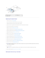
Back to Contents Page System Board Dell™ Inspiron™ One 2205 Service Manual Removing the System Board Replacing the System Board Entering the Service Tag in the BIOS WARNING: Before working inside your computer, read the safety information that shipped with your computer. For additional safety best practices information, see the Regulatory Compliance Homepage at www.dell.com/regulatory_compliance. CAUTION: Only a certified service technician should perform repairs on your computer. Damage due to servicing that is not authorized by Dell™ is not covered by your warranty. CAUTION: To avoid electrostatic discharge, ground yourself by using a wrist grounding strap or by periodically touching an unpainted metal surface (such as a connector on your computer). CAUTION: Handle components and cards by their edges, and avoid touching pins and contacts. Removing the System Board 1. Follow the instructions in Before You Begin. 2. Remove the back cover (see Removing the Back Cover). 3. Follow the instructions from step 3 to step 7 in Removing the Front Stand. 4. Remove the rear stand cover (see Removing the Rear Stand Cover). 5. Remove the system-board shield (see Removing the System-Board Shield). 6. Remove the MXM-assembly fan (see Removing the MXM-Assembly Fan). 7. Remove the MXM assembly (see Removing the MXM Assembly). 8. Remove the memory module(s) (see Removing Memory Module(s)). 9. Remove the Mini-Card(s) (see Removing the Mini-Card(s)). 10. Remove the processor heat-sink fan (see Removing the Processor Heat-Sink Fan). 11. Remove the processor heat-sink (see Removing the Processor Heat-Sink). 12. Remove the processor (see Removing the Processor). NOTE: Make note of the cable routing before disconnecting the cables from the system board. 13. Disconnect all the cables connected to the system board. 14. Using a hex nut driver, remove the two hex nut screws that secure the system board to the chassis. 15. Remove the eight screws that secure the system board to the chassis. 16. Lift the system board at an angle toward the side of the computer and out of the chassis.
-
 1
1 -
2
-
3
-
4
-
5
-
6
-
7
-
8
-
9
-
10
-
11
-
12
-
13
-
14
-
15
-
16
-
17
-
18
-
19
-
20
-
21
-
22
-
23
-
24
-
25
-
26
-
27
-
28
-
29
-
30
-
31
-
32
-
33
-
34
-
35
-
36
-
37
-
38
-
39
-
40
-
41
-
42
-
43
-
44
-
45
-
46
-
47
-
48
-
49
-
50
-
51
-
52
-
53
-
54
-
 55
55 -
 56
56 -
 57
57 -
 58
58 -
 59
59 -
 60
60 -
 61
61 -
 62
62 -
 63
63 -
 64
64 -
 65
65 -
66
-
67
-
68
-
69
-
70
-
71
-
72
-
73
-
74
 |
 |