Dell Inspiron One 2205 Service Manual - Page 18
Display Panel
 |
View all Dell Inspiron One 2205 manuals
Add to My Manuals
Save this manual to your list of manuals |
Page 18 highlights
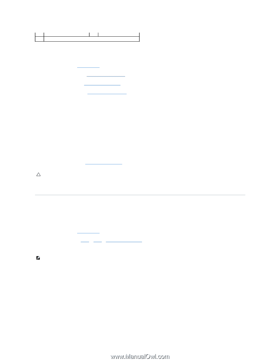
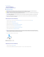
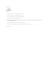
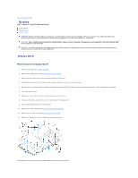
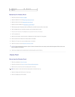
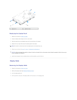
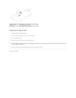
1 display bezel 3 tabs (3) 2 screws (19) Replacing the Display Bezel 1. Follow the instructions in Before You Begin. 2. Replace the Bluetooth card (see Replacing the Bluetooth Card). 3. Replace the infrared card (see Replacing the Infrared Card). 4. Replace the camera module (see Replacing the Camera Module). 5. Slide the camera cable, infrared-card cable, and Bluetooth-card cable through the slots on the chassis. 6. Align the display bezel over the display and gently snap the display bezel into place. 7. Ensure that the three tabs on the display bezel are secured to the slots on the chassis. 8. Turn the computer over. 9. Route the camera cable, infrared-card cable, and Bluetooth-card cable through the routing guides. 10. Secure the silver foil that adheres the camera module to the chassis. 11. Replace the 19 screws that secure the display bezel to the chassis. 12. Replace the system board (see Replacing the System Board). CAUTION: Before turning on the computer, replace all screws and ensure that no stray screws remain inside the computer. Failure to do so may result in damage to the computer. 13. Connect your computer and all attached devices to electrical outlets, and turn them on. Display Panel Removing the Display Panel 1. Follow the instructions in Before You Begin. 2. Follow the instructions from step 2 to step 9 in Removing the Display Bezel. 3. Remove the four screws that secure the display panel to the chassis. NOTE: The number of screws that secure the display panel to the chassis may vary. 4. Remove the display cable from the slot on the chassis. 5. Remove the display panel off the chassis.
-
 1
1 -
2
-
3
-
4
-
5
-
6
-
7
-
8
-
9
-
10
-
11
-
12
-
 13
13 -
 14
14 -
 15
15 -
 16
16 -
 17
17 -
 18
18 -
 19
19 -
 20
20 -
 21
21 -
 22
22 -
 23
23 -
24
-
25
-
26
-
27
-
28
-
29
-
30
-
31
-
32
-
33
-
34
-
35
-
36
-
37
-
38
-
39
-
40
-
41
-
42
-
43
-
44
-
45
-
46
-
47
-
48
-
49
-
50
-
51
-
52
-
53
-
54
-
55
-
56
-
57
-
58
-
59
-
60
-
61
-
62
-
63
-
64
-
65
-
66
-
67
-
68
-
69
-
70
-
71
-
72
-
73
-
74
 |
 |