Haier 3U19FS1ERA Service Manual - Page 56
Floor Console Type
 |
View all Haier 3U19FS1ERA manuals
Add to My Manuals
Save this manual to your list of manuals |
Page 56 highlights
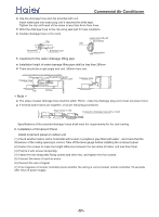
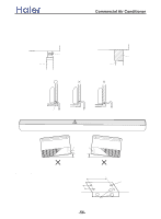
>_]]VbTZR\ _^UZdZ_^Vb PREPARING INDOOR UNIT INSTALLATION REMOVE THE INTAKE GRILL Open the intake grill and remove the three or four or six screws.(Fig. 1) Fig. 1 Intake grill Remark: The main unit can be wired before the indoor unit is installed. Select the most appropriate installation order. A. FLOOR CONSOLE TYPE 1. DRILLING FOR PIPING Select piping and drain directions.(Fig.2) The piping and drain can be made in three directions as shown below. When the directions are selected, drill a 7 cm dia. hole on the wall so that the hole is tilted downward toward the outdoor for smooth water flow. When the pipe is led out from the rear, make a hole in Fig.4, at the position shown. (Fig.2) rear right down The drain hose can be connected to either the left or right side.(Fig.3) (Fig.4) Wall 7cm Indoor unit 6mm outdoor unit When installing set to wall, install the accessory wall bracket at the position shown in Fig.5,and mount the set to it. (Fig. 3) (Fig. 5) Drain hose (Left side) Drain hose (Right side) 99cm 50cm 24.5cm Wall bracket 6.5cm 7cm hole 3.5cm hole Side of set 12.5cm 10cm -55-
-
 1
1 -
2
-
3
-
4
-
5
-
6
-
7
-
8
-
9
-
10
-
11
-
12
-
13
-
14
-
15
-
16
-
17
-
18
-
19
-
20
-
21
-
22
-
23
-
24
-
25
-
26
-
27
-
28
-
29
-
30
-
31
-
32
-
33
-
34
-
35
-
36
-
37
-
38
-
39
-
40
-
41
-
42
-
43
-
44
-
45
-
46
-
47
-
48
-
49
-
50
-
 51
51 -
 52
52 -
 53
53 -
 54
54 -
 55
55 -
 56
56 -
 57
57 -
 58
58 -
 59
59 -
 60
60 -
 61
61 -
62
-
63
-
64
-
65
-
66
-
67
-
68
-
69
-
70
-
71
-
72
-
73
-
74
-
75
-
76
-
77
-
78
-
79
-
80
-
81
-
82
-
83
-
84
-
85
-
86
-
87
-
88
-
89
-
90
-
91
-
92
-
93
-
94
-
95
-
96
-
97
-
98
-
99
-
100
-
101
-
102
-
103
-
104
-
105
-
106
-
107
-
108
-
109
-
110
-
111
-
112
-
113
-
114
-
115
-
116
-
117
-
118
-
119
-
120
-
121
-
122
-
123
-
124
-
125
-
126
-
127
-
128
-
129
-
130
-
131
-
132
-
133
-
134
-
135
-
136
-
137
 |
 |
