Haier 3U19FS1ERA Service Manual - Page 98
Trouble Shooting
 |
View all Haier 3U19FS1ERA manuals
Add to My Manuals
Save this manual to your list of manuals |
Page 98 highlights
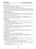
>_]]VbTZR\ _^UZdZ_^Vb 6.2. Trouble Shooting: Trouble 1: No display on the operation panel start check if display panel and the unit matched well yes if the red diode and green diode on indoor PCB flash in turn yes PCB is faulty, no check if display panel is 12V replace it power supply no replace display panel and check again if the power check the terminal no terminal block is no block and the 220V input power supply yes check if power wiring is in open no check if fuse is circuit burnt no PCB is faulty, replace yes display panel circuit is damaged, replace it yes replace power wiring and check again yes replace the fuse and check again Trouble 2: Sensor failure start as per the wiring diagram,check the connection between sensor and PCB is correct yes check if sensor is in open circuit or PCB port is not in good condition yes replace sensor and check again no re-fix the sensor and check again no check if sensor no resistor value is correct yes PCB is faulty and repalce it, check again replace sensor and check again -97-
-
 1
1 -
2
-
3
-
4
-
5
-
6
-
7
-
8
-
9
-
10
-
11
-
12
-
13
-
14
-
15
-
16
-
17
-
18
-
19
-
20
-
21
-
22
-
23
-
24
-
25
-
26
-
27
-
28
-
29
-
30
-
31
-
32
-
33
-
34
-
35
-
36
-
37
-
38
-
39
-
40
-
41
-
42
-
43
-
44
-
45
-
46
-
47
-
48
-
49
-
50
-
51
-
52
-
53
-
54
-
55
-
56
-
57
-
58
-
59
-
60
-
61
-
62
-
63
-
64
-
65
-
66
-
67
-
68
-
69
-
70
-
71
-
72
-
73
-
74
-
75
-
76
-
77
-
78
-
79
-
80
-
81
-
82
-
83
-
84
-
85
-
86
-
87
-
88
-
89
-
90
-
91
-
92
-
 93
93 -
 94
94 -
 95
95 -
 96
96 -
 97
97 -
 98
98 -
 99
99 -
 100
100 -
 101
101 -
 102
102 -
 103
103 -
104
-
105
-
106
-
107
-
108
-
109
-
110
-
111
-
112
-
113
-
114
-
115
-
116
-
117
-
118
-
119
-
120
-
121
-
122
-
123
-
124
-
125
-
126
-
127
-
128
-
129
-
130
-
131
-
132
-
133
-
134
-
135
-
136
-
137
 |
 |
