Haier 3U19FS1ERA Service Manual - Page 62
Electrical Wiring
 |
View all Haier 3U19FS1ERA manuals
Add to My Manuals
Save this manual to your list of manuals |
Page 62 highlights
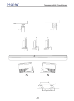
ELECTRICAL WIRING CAUTION (1) Match the terminal block numbers and connection cord colors with those of the outdoor unit. Erroneous wiring may cause burning of the electric parts. (2) Connect the connection cords firmly to the terminal block. Imperfect installation may cause a fire. (3) Always fasten the outside covering of the connection cord with the cord clamp.(If the insulator is chafed, electric leakage may occur.) (4) Always connect the ground wire. >_]]VbTZR\ _^UZdZ_^Vb (2) Pull out the electric component box. Fig.28 (3) Remove the electric component box cover. Fig. 29 1. INDOOR UNIT SIDE (1) Remove the electric component box. Fig. 26 Base Electric component box cover Remove the three tapping screws. CAUTION Be careful not to pinch the lead wires between the electric component box and base. Fig. 27 Electric component box Remove the four tapping screws. CAUTION Do not remove the screws. If the screws are removed, the electric component box will fall. (4) Wiring (1) Remove the cord clamp. (2) Process the end of the connection cords to the dimensions shown in Fig.34. (3) Connect the end of the connection cord fully into the terminal block. (4) Fasten the connection cord with a cord clamp. (5) Fasten the end of the connection cord with the screw. -61-
-
 1
1 -
2
-
3
-
4
-
5
-
6
-
7
-
8
-
9
-
10
-
11
-
12
-
13
-
14
-
15
-
16
-
17
-
18
-
19
-
20
-
21
-
22
-
23
-
24
-
25
-
26
-
27
-
28
-
29
-
30
-
31
-
32
-
33
-
34
-
35
-
36
-
37
-
38
-
39
-
40
-
41
-
42
-
43
-
44
-
45
-
46
-
47
-
48
-
49
-
50
-
51
-
52
-
53
-
54
-
55
-
56
-
 57
57 -
 58
58 -
 59
59 -
 60
60 -
 61
61 -
 62
62 -
 63
63 -
 64
64 -
 65
65 -
 66
66 -
 67
67 -
68
-
69
-
70
-
71
-
72
-
73
-
74
-
75
-
76
-
77
-
78
-
79
-
80
-
81
-
82
-
83
-
84
-
85
-
86
-
87
-
88
-
89
-
90
-
91
-
92
-
93
-
94
-
95
-
96
-
97
-
98
-
99
-
100
-
101
-
102
-
103
-
104
-
105
-
106
-
107
-
108
-
109
-
110
-
111
-
112
-
113
-
114
-
115
-
116
-
117
-
118
-
119
-
120
-
121
-
122
-
123
-
124
-
125
-
126
-
127
-
128
-
129
-
130
-
131
-
132
-
133
-
134
-
135
-
136
-
137
 |
 |
