Haier 3U19FS1ERA Service Manual - Page 61
How To Connect Wiring To The Terminals, How To Fixed Connection Cord And Power Cable At, The Cord
 |
View all Haier 3U19FS1ERA manuals
Add to My Manuals
Save this manual to your list of manuals |
Page 61 highlights
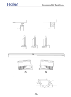
>_]]VbTZR\ _^UZdZ_^Vb HOW TO CONNECT WIRING TO THE TERMINALS A. For solid core wiring (or F-cable)(Fig.24A) (1) Cut the wire with a wire cutter or wire-cutting pliers, then strip the insulation to about 25mm of the exposed solid wire. (2) Using a screwdriver, remove the terminal screw(s) on the terminal board. (3) Using pliers, bend the solid wire to form a loop suitable for the terminal screw. (4) Shape the loop wire properly, place it on the terminal board and tighten securely with the terminal screw using a screw driver. B. For strand wiring(Fig.24B) (1) Cut the wire with a wire cutter or wire-cutting pliers, then strip the insulation to about 10mm of the exposed strand wiring. (2) Using a screwdriver, remove the terminal screw(s)on the terminal board. (3) Using a round terminal fastener or pliers, securely clamp a round terminal to each stripped wire end. (4) Position the round terminal wire, and replace and tighten the terminal screw using a screw driver. Fig. 24 A. Solid wire Loop B. Strand wire Round terminal Insulation Screw with special washer Round terminal Terminal Wire board Wire Screw with special washer Round terminal HOW TO FIXED CONNECTION CORD AND POWER CABLE AT THE CORD CLAMP After passing the connection cord and power cable through the insulation tube, fasten it with the cord clamp, as shown in Fig.25 Fig. 25 Insulation tube Cord clamp Use VW-1, 0.5 to 1.0 mm thick, PVC tube as the insulation tube. -60-
-
 1
1 -
2
-
3
-
4
-
5
-
6
-
7
-
8
-
9
-
10
-
11
-
12
-
13
-
14
-
15
-
16
-
17
-
18
-
19
-
20
-
21
-
22
-
23
-
24
-
25
-
26
-
27
-
28
-
29
-
30
-
31
-
32
-
33
-
34
-
35
-
36
-
37
-
38
-
39
-
40
-
41
-
42
-
43
-
44
-
45
-
46
-
47
-
48
-
49
-
50
-
51
-
52
-
53
-
54
-
55
-
 56
56 -
 57
57 -
 58
58 -
 59
59 -
 60
60 -
 61
61 -
 62
62 -
 63
63 -
 64
64 -
 65
65 -
 66
66 -
67
-
68
-
69
-
70
-
71
-
72
-
73
-
74
-
75
-
76
-
77
-
78
-
79
-
80
-
81
-
82
-
83
-
84
-
85
-
86
-
87
-
88
-
89
-
90
-
91
-
92
-
93
-
94
-
95
-
96
-
97
-
98
-
99
-
100
-
101
-
102
-
103
-
104
-
105
-
106
-
107
-
108
-
109
-
110
-
111
-
112
-
113
-
114
-
115
-
116
-
117
-
118
-
119
-
120
-
121
-
122
-
123
-
124
-
125
-
126
-
127
-
128
-
129
-
130
-
131
-
132
-
133
-
134
-
135
-
136
-
137
 |
 |
