HP BL10e HP ProLiant BL e-Class System Setup and Installation Guide
HP BL10e - ProLiant - G2 Manual
 |
UPC - 808736933599
View all HP BL10e manuals
Add to My Manuals
Save this manual to your list of manuals |
HP BL10e manual content summary:
- HP BL10e | HP ProLiant BL e-Class System Setup and Installation Guide - Page 1
HP ProLiant BL e-Class System Setup and Installation Guide May 2003 (Third Edition) Part Number 249068-003 - HP BL10e | HP ProLiant BL e-Class System Setup and Installation Guide - Page 2
. The warranties for HP products are set forth in the express limited warranty statements accompanying such products. Nothing herein should be construed as constituting an additional warranty. HP ProLiant BL e-Class System Setup and Installation Guide May 2003 (Third Edition) Part Number 249068-003 - HP BL10e | HP ProLiant BL e-Class System Setup and Installation Guide - Page 3
Enclosure Features 1-4 ProLiant BL e-Class Server Blade Features 1-7 Software Deployment and Management Features 1-11 Diagnostic Features ...1-14 Pre-Failure Warranty ...1-14 Chapter 2 Planning the Installation Optimum Environment...2-1 Rack Warnings ...2-2 HP ProLiant BL e-Class System Setup - HP BL10e | HP ProLiant BL e-Class System Setup and Installation Guide - Page 4
Deployment Using HP ProLiant Essentials Rapid Deployment Pack ....4-2 Alternate Deployment Methods 4-3 Diagnostic Adapter...4-4 ProLiant BL e-Class Server Blade Supported Software Utilities 4-4 Supported Operating Systems 4-4 iv HP ProLiant BL e-Class System Setup and Installation Guide - HP BL10e | HP ProLiant BL e-Class System Setup and Installation Guide - Page 5
Setup Utility 4-5 Redundant ROM Support 4-6 Flashing the Server Blade ROM 4-8 ProLiant BL e-Class Integrated Administrator 4-10 Server Blade Event Messages 4-13 Insight Manager 7 4-15 Survey Utility...4-16 ProLiant Methods...B-2 HP ProLiant BL e-Class System Setup and Installation Guide v - HP BL10e | HP ProLiant BL e-Class System Setup and Installation Guide - Page 6
...E-15 Front Panel ...E-16 Rear Panel ...E-17 Server Blade Maintenance Switch E-18 Appendix F Specifications Server Blade Enclosure...F-2 Hot-Plug Power Supply F-3 Appendix G System Battery Server Blade Battery Replacement G-1 Index vi HP ProLiant BL e-Class System Setup and Installation Guide - HP BL10e | HP ProLiant BL e-Class System Setup and Installation Guide - Page 7
ProLiant BL10e server blade DIMM socket keys 3-31 3-25 ProLiant BL10e G2 server blade DIMM socket keys 3-32 3-26 Removing a DIMM 3-33 3-27 Installing a DIMM 3-34 3-28 Attaching the diagnostic adapter 3-35 3-29 Connectors on the diagnostic adapter 3-36 HP ProLiant BL e-Class System Setup and - HP BL10e | HP ProLiant BL e-Class System Setup and Installation Guide - Page 8
LED Green D-13 D-9 Server Blade Diagnostic Steps D-15 D-10 Is the Power LED on the Server Blade Green D-16 D-11 Is the Health LED on the Server Blade Green D-17 D-12 Is the NIC 1 or NIC 2 LED on the Server Blade Illuminated D-18 viii HP ProLiant BL e-Class System Setup and Installation Guide - HP BL10e | HP ProLiant BL e-Class System Setup and Installation Guide - Page 9
E-14 Enclosure Front Panel Buttons E-16 Enclosure Rear Panel Buttons E-17 Server Blade Maintenance Switches E-18 Enclosure Operating and Performance Specifications F-2 Hot-Plug Power Supply Operating and Performance Specifications F-3 HP ProLiant BL e-Class System Setup and Installation Guide - HP BL10e | HP ProLiant BL e-Class System Setup and Installation Guide - Page 10
instructions for installation and reference information for operation, troubleshooting, and future upgrades for the HP ProLiant BL e-Class system. Audience Assumptions This guide is for the person who installs, administers, and troubleshoots servers. HP assumes you are qualified in the servicing - HP BL10e | HP ProLiant BL e-Class System Setup and Installation Guide - Page 11
user or field serviceable parts. Do not open for any reason. WARNING: To reduce the risk of injury from electric shock hazards, do not open this enclosure. This symbol safety requirements and guidelines for manual material handling. xii HP ProLiant BL e-Class System Setup and Installation Guide - HP BL10e | HP ProLiant BL e-Class System Setup and Installation Guide - Page 12
for any reason. Symbols in Text These symbols may be found in the text of this guide. They have the following meanings. WARNING: Text set off in this manner indicates that emphasize or supplement important points of the main text. HP ProLiant BL e-Class System Setup and Installation Guide xiii - HP BL10e | HP ProLiant BL e-Class System Setup and Installation Guide - Page 13
and Service Guide • HP ProLiant BL e-Class System Hardware Installation and Configuration poster • HP ProLiant BL e-Class Integrated Administrator User Guide • ProLiant Integration Module for Altiris eXpress User Guide • HP Servers Troubleshooting Guide • HP ROM-Based Setup Utility User Guide • HP - HP BL10e | HP ProLiant BL e-Class System Setup and Installation Guide - Page 14
, call 1-800-263-5868. • Elsewhere, see the HP website for locations and telephone numbers. Reader's Comments HP welcomes your comments on this guide. Please send your comments and suggestions by e-mail to [email protected]. HP ProLiant BL e-Class System Setup and Installation Guide xv - HP BL10e | HP ProLiant BL e-Class System Setup and Installation Guide - Page 15
The HP ProLiant BL e-Class server blade system offers space- and power-efficient performance and serviceability in a 3U rack-mounted enclosure. This state-of-the-art modular system supports rapid server configuration and deployment flexibility. ProLiant BL e-Class System Technology The ProLiant BL - HP BL10e | HP ProLiant BL e-Class System Setup and Installation Guide - Page 16
, network fault tolerance, or load balancing • Rapid servicing - Modular component design enables easy upgrades and service - Major components accessible from the front and rear of the enclosure - Support for in-rack diagnostic methods 1-2 HP ProLiant BL e-Class System Setup and Installation Guide - HP BL10e | HP ProLiant BL e-Class System Setup and Installation Guide - Page 17
ProLiant BL e-Class server blade enclosure with ProLiant BL e-Class server blades (20) The enclosure and server blade features described in the following sections are standard on all ProLiant BL e-Class systems, unless otherwise specified. HP ProLiant BL e-Class System Setup and Installation Guide - HP BL10e | HP ProLiant BL e-Class System Setup and Installation Guide - Page 18
• Remote power on/off/reboot and Unit Identification (UID) controls • Access to any server blade remote console • Access to any server blade ROM-Based Setup Utility (RBSU) • Support for command line scripting • Upgradeable firmware 1-4 HP ProLiant BL e-Class System Setup and Installation Guide - HP BL10e | HP ProLiant BL e-Class System Setup and Installation Guide - Page 19
connectors) • Interconnect tray form factor that fits into server blade enclosure • Low wattage for maximum power efficiency • Compatibility with common core switches • Two separate switches providing redundant paths to each server blade HP ProLiant BL e-Class System Setup and Installation Guide - HP BL10e | HP ProLiant BL e-Class System Setup and Installation Guide - Page 20
is displayed locally through a full set of system LEDs, including: • Internal fan health LEDs • External health LEDs - Fan health LED - Enclosure health LED - Server blade LEDs - Power supply LEDs - Integrated Administrator health LED 1-6 HP ProLiant BL e-Class System Setup and Installation Guide - HP BL10e | HP ProLiant BL e-Class System Setup and Installation Guide - Page 21
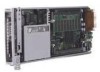
, deploy, and service. A server blade that requires out-of-the-rack upgrades, service, or maintenance can be easily replaced by another server blade. Figure 1-2: ProLiant BL10e server blade Figure 1-3: ProLiant BL10e G2 server blade HP ProLiant BL e-Class System Setup and Installation Guide 1-7 - HP BL10e | HP ProLiant BL e-Class System Setup and Installation Guide - Page 22
BL10e server blade; Registered DDR SDRAM memory for the ProLiant BL10e G2 server blade For more information, refer to QuickSpecs located on the HP website: www.hp.com • ECC memory - Detects and corrects single-bit memory errors 1-8 HP ProLiant BL e-Class System Setup and Installation Guide - HP BL10e | HP ProLiant BL e-Class System Setup and Installation Guide - Page 23
health LED • Server blade network activity LEDs • Hard drive activity LED • Power button and LED • Diagnostic support through ROM-Based Setup Utility (RBSU), the Integrated Management Log (IML), health driver, and Insight Manager 7 Diagnostic Adapter Each server blade has a diagnostic connector that - HP BL10e | HP ProLiant BL e-Class System Setup and Installation Guide - Page 24
eXecution Environment (PXE) support • Wake-on-LAN (WOL) • Auto-negotiation of 10/100-Mbps link speeds • Full-duplex Ethernet support • Teaming for network fault tolerance or load balancing (also known as port bonding or trunking) 1-10 HP ProLiant BL e-Class System Setup and Installation Guide - HP BL10e | HP ProLiant BL e-Class System Setup and Installation Guide - Page 25
provides intuitive drag-and-drop events, such as scripts and images, to deploy the operating systems and applications on any combination of server blades installed in the enclosures - Simultaneous deployment of multiple server blades HP ProLiant BL e-Class System Setup and Installation Guide 1-11 - HP BL10e | HP ProLiant BL e-Class System Setup and Installation Guide - Page 26
blades and interconnect tray are not affected by ESR. • Integrated Management Log (IML) The IML provides a detailed log of key system events. This log, which also monitors the server health log, is accessible by utilities, including Insight Manager 7. 1-12 HP ProLiant BL e-Class System Setup - HP BL10e | HP ProLiant BL e-Class System Setup and Installation Guide - Page 27
the number of network cables connected to the enclosure. The interconnect switch is compatible with industry standards and is fully pre-configured for immediate use. For more information about these tools and utilities, see Chapter 4, "Deployment and Management." HP ProLiant BL e-Class System Setup - HP BL10e | HP ProLiant BL e-Class System Setup and Installation Guide - Page 28
that a component is in a degraded condition and prompts you to replace the component in its pre-failure condition. For specific coverage information, refer to the warranty card that ships with the ProLiant BL e-class server blades. 1-14 HP ProLiant BL e-Class System Setup and Installation Guide - HP BL10e | HP ProLiant BL e-Class System Setup and Installation Guide - Page 29
• Power • Electrical grounding • Temperature • Airflow For detailed information on these requirements, refer to the HP ProLiant BL e-Class System Overview and Planning white paper on the Documentation CD and at the HP website: www.hp.com HP ProLiant BL e-Class System Setup and Installation Guide - HP BL10e | HP ProLiant BL e-Class System Setup and Installation Guide - Page 30
When using a Compaq branded 7000 Series rack, you must install the high airflow rack door insert [P/N 327281-B21 (for 42U rack) and P/N 157847-B21 (for 22U rack)] to provide proper front-to-back airflow and cooling and to prevent damage to the equipment. 2-2 HP ProLiant BL e-Class System Setup and - HP BL10e | HP ProLiant BL e-Class System Setup and Installation Guide - Page 31
an HP or third-party rack is used, observe the following additional requirements to ensure adequate airflow and to prevent damage to the equipment: • Front and rear doors: If the 42U server cooling that can lead to thermal damage. HP ProLiant BL e-Class System Setup and Installation Guide 2-3 - HP BL10e | HP ProLiant BL e-Class System Setup and Installation Guide - Page 32
personnel have access to the server. WARNING: To reduce the risk of electric shock or damage to the equipment: • Only enter or perform service on specific parts of the ProLiant BL e-Class system as instructed in the user documentation. • Do not disable the power cord grounding plugs. The grounding - HP BL10e | HP ProLiant BL e-Class System Setup and Installation Guide - Page 33
people support the weight of the enclosure. WARNING: The ProLiant BL e-Class server blade enclosure has two power cords for redundant AC power sources. If it is necessary to remove power for servicing, disconnect all power by removing both power supply cords from either the wall or the AC connectors - HP BL10e | HP ProLiant BL e-Class System Setup and Installation Guide - Page 34
are PXE-enabled, and the server blades support a bootable USB diskette drive (attached using the diagnostic adapter). Shipping Contents IMPORTANT: All the rack mounting hardware necessary for installing the ProLiant BL e-Class server blade enclosure into an HP, Compaq branded, or third-party rack - HP BL10e | HP ProLiant BL e-Class System Setup and Installation Guide - Page 35
Class server blade enclosure ships with the following: • Two redundant hot-plug power supplies and power cords • Four redundant hot-plug fans • Server blade blanks • Two diagnostic adapters • ProLiant Essentials Foundation Pack for ProLiant BL Servers • Rack mounting hardware for HP, Compaq branded - HP BL10e | HP ProLiant BL e-Class System Setup and Installation Guide - Page 36
rack mounting hardware (for HP, Compaq branded, and third-party racks) that ships with the ProLiant BL e-Class server blade enclosure. When shipping a server blade enclosure installed in a rack, secure the enclosure to the rack using the shipping bracket option kit (part number 293119-B21). Refer to - HP BL10e | HP ProLiant BL e-Class System Setup and Installation Guide - Page 37
Blades Server blades ship in packages of one or ten server blades. Interconnect Trays The ProLiant BL e-Class system supports an interconnect tray offered in a choice of configurations: 1 2 3 Figure 2-2: The available interconnect trays HP ProLiant BL e-Class System Setup and Installation Guide - HP BL10e | HP ProLiant BL e-Class System Setup and Installation Guide - Page 38
In the United States, HP makes all the arrangements to have the ProLiant BL e-Class system installed by qualified guaranteed service providers. For ordering information, refer to the HP Care Pack website: www.hp.com/services/carepack 2-10 HP ProLiant BL e-Class System Setup and Installation Guide - HP BL10e | HP ProLiant BL e-Class System Setup and Installation Guide - Page 39
system • Powering down the ProLiant BL e-Class system - Powering down a server blade - Powering down the enclosure • Installing a server blade • Removing a server blade • Installing additional memory • Attaching the diagnostic adapter HP ProLiant BL e-Class System Setup and Installation Guide 3-1 - HP BL10e | HP ProLiant BL e-Class System Setup and Installation Guide - Page 40
indicates hot-plug components. 2. Open the handle (2). 3. Slide the hot-plug power supply out of the enclosure (3). Figure 3-1: Removing a hot-plug power supply 4. Repeat steps 1 through 3 to remove the other hot-plug power supply. 3-2 HP ProLiant BL e-Class System Setup and Installation Guide - HP BL10e | HP ProLiant BL e-Class System Setup and Installation Guide - Page 41
the interconnect tray release buttons (1). 6. Pull the slate blue ejector levers toward the rear of the enclosure (2). NOTE: Slate blue indicates internal touch point components. Figure 3-2: Pulling the interconnect tray ejector levers HP ProLiant BL e-Class System Setup and Installation Guide 3-3 - HP BL10e | HP ProLiant BL e-Class System Setup and Installation Guide - Page 42
and Cabling the System 7. Insert the interconnect tray into the enclosure (1). 8. Rotate the interconnect tray levers to the locked position (2). Figure 3-3: Inserting the interconnect tray and engaging the interconnect tray levers 3-4 HP ProLiant BL e-Class System Setup and Installation Guide - HP BL10e | HP ProLiant BL e-Class System Setup and Installation Guide - Page 43
9. Install the hot-plug power supplies (1). 10. Close the power supply handles (2). Installing and Cabling the System Figure 3-4: Installing a hot-plug power supply HP ProLiant BL e-Class System Setup and Installation Guide 3-5 - HP BL10e | HP ProLiant BL e-Class System Setup and Installation Guide - Page 44
bottom of the rack and work your way up with additional enclosures as needed. IMPORTANT: Match the hole pattern on the rack template with the holes in the rack supports. Figure 3-5: Measuring with the ProLiant BL e-Class rack template 3-6 HP ProLiant BL e-Class System Setup and Installation Guide - HP BL10e | HP ProLiant BL e-Class System Setup and Installation Guide - Page 45
the rack. IMPORTANT: Tick marks on the rack supports help you to maintain proper alignment of the rack template the rack template for the next enclosure (2). Figure 3-6: Marking the rack for ProLiant BL e-Class system installation 6. HP ProLiant BL e-Class System Setup and Installation Guide 3-7 - HP BL10e | HP ProLiant BL e-Class System Setup and Installation Guide - Page 46
rack using the numbers on the rack rail as a guide (3). The depth of a Compaq branded rack (29 Numbers on the rack rail provide a gross adjustment of the depth of the rack. The rack rail may need to be tightened to ensure proper fit. 3-8 HP ProLiant BL e-Class System Setup and Installation Guide - HP BL10e | HP ProLiant BL e-Class System Setup and Installation Guide - Page 47
feature "L" and "R" markings to identify the left and right rack rails (from the front of the rack). Figure 3-8: Inserting the rear of the rack rail HP ProLiant BL e-Class System Setup and Installation Guide 3-9 - HP BL10e | HP ProLiant BL e-Class System Setup and Installation Guide - Page 48
obtain a correct fit may result in damage to equipment. Once the right rack rail is properly installed, begin installation of the left rack rail. 3-10 HP ProLiant BL e-Class System Setup and Installation Guide - HP BL10e | HP ProLiant BL e-Class System Setup and Installation Guide - Page 49
the enclosure into the rack: 1. Install the interconnect tray. See the "Installing the Interconnect Tray" section in this chapter. 2. Stand at the front of the rack. 3. Align the bottom of the enclosure with the top of the rack rails. HP ProLiant BL e-Class System Setup and Installation Guide 3-11 - HP BL10e | HP ProLiant BL e-Class System Setup and Installation Guide - Page 50
white hexagonal washers, which are compatible with Compaq branded racks and some HP and third-party racks • Size M6 thumbscrews with black hexagonal washers, which are compatible with some third-party racks that require metric sizes 3-12 HP ProLiant BL e-Class System Setup and Installation Guide - HP BL10e | HP ProLiant BL e-Class System Setup and Installation Guide - Page 51
outward while unscrewing the head of the screw (1). 2. Remove the head of the screw (2). 3. Remove the hexagonal washer (3). Figure 3-11: Removing a thumbscrew and hexagonal washer HP ProLiant BL e-Class System Setup and Installation Guide 3-13 - HP BL10e | HP ProLiant BL e-Class System Setup and Installation Guide - Page 52
. External cabling depends on the type of interconnect tray installed in the system. The procedure for cabling an enclosure consists of the following steps: • Identifying the interconnect tray connectors • Cabling the server blade enclosure 3-14 HP ProLiant BL e-Class System Setup and Installation - HP BL10e | HP ProLiant BL e-Class System Setup and Installation Guide - Page 53
GbE Interconnect Switch Connectors The interconnect switch reduces 40 10/100 Ethernet networking connections coming from the server blades to four Gigabit Ethernet uplink RJ-45 connectors. Figure 3-13: Interconnect switch connectors HP ProLiant BL e-Class System Setup and Installation Guide 3-15 - HP BL10e | HP ProLiant BL e-Class System Setup and Installation Guide - Page 54
module. RJ-21 Patch Panel Connectors The RJ-21 patch panel features a simplified connector configuration that consolidates the server blade network connections into four RJ-21 connectors. Figure 3-14: RJ-21 patch panel connectors 3-16 HP ProLiant BL e-Class System Setup and Installation - HP BL10e | HP ProLiant BL e-Class System Setup and Installation Guide - Page 55
connectors for the Integrated Administrator module. RJ-45 Patch Panel Connectors The RJ-45 patch panel features two RJ-45 connectors for each server blade, for a total of 40 RJ-45 connectors. Figure 3-15: RJ-45 patch panel connectors HP ProLiant BL e-Class System Setup and Installation Guide - HP BL10e | HP ProLiant BL e-Class System Setup and Installation Guide - Page 56
module. Cabling the Enclosure To cable a ProLiant BL e-Class server blade enclosure already installed in a rack: CAUTION: Do not connect external devices to the enclosure link (RJ-45) connectors unless the device is listed as a supported device on the server Quickspecs. Connecting an unsupported - HP BL10e | HP ProLiant BL e-Class System Setup and Installation Guide - Page 57
RJ-45 connector for each server blade provides PXE-enabled connectivity by default. 3. Connect an AC power cord to each hot-plug power supply. Note that the enclosure will power up as soon as an AC power cord is connected to a power source and a power supply. HP ProLiant BL e-Class System Setup and - HP BL10e | HP ProLiant BL e-Class System Setup and Installation Guide - Page 58
Installing and Cabling the System 4. Bundle network and power cables together and route them to the outer edge of the rack. Figure 3-16: Cabling the system with the interconnect switch 3-20 HP ProLiant BL e-Class System Setup and Installation Guide - HP BL10e | HP ProLiant BL e-Class System Setup and Installation Guide - Page 59
the cables for the enclosure in a manner that provides rapid, easy access to the console connector for a local client device, such as a laptop computer. 5. Repeat steps 1 through 4 for each server blade enclosure you have installed. HP ProLiant BL e-Class System Setup and Installation Guide 3-21 - HP BL10e | HP ProLiant BL e-Class System Setup and Installation Guide - Page 60
Cable Kit (Option) HP offers a set of four cables (257076-B21), each of which connects ten RJ-45 connectors to a single RJ-21 connector for use with the RJ-21 patch panel. Use Table 3-4 to determine the specifications of this cable. Table 3-4: Cable Pinout (Sample for Server Blades 1 through 10 NIC - HP BL10e | HP ProLiant BL e-Class System Setup and Installation Guide - Page 61
a server blade blank and install a server blade into the front panel of the enclosure, the server blade powers up. Powering Down the ProLiant BL e-Class System You can power down one or more server blades or the entire enclosure. HP ProLiant BL e-Class System Setup and Installation Guide 3-23 - HP BL10e | HP ProLiant BL e-Class System Setup and Installation Guide - Page 62
Pressing the power button on the front of the server blade IMPORTANT: Refer to the HP ProLiant BL e-Class Integrated Administrator User Guide to power down the server blade using the Integrated Administrator. Figure 3-19: Powering down the server blade 3-24 HP ProLiant BL e-Class System Setup and - HP BL10e | HP ProLiant BL e-Class System Setup and Installation Guide - Page 63
configuration and server deployment process. See Chapter 4, "Deployment and Management." 2. Install or upgrade memory before installing server blades into an enclosure. See the "Installing Additional Memory" section in this chapter. HP ProLiant BL e-Class System Setup and Installation Guide - HP BL10e | HP ProLiant BL e-Class System Setup and Installation Guide - Page 64
improper cooling and thermal damage. 3. Remove the server blade blank: a. Press the ejector tabs on the server blade blank (1). b. Slide the server blade blank out of the bay (2). Figure 3-20: Removing a single-bay server blade blank 3-26 HP ProLiant BL e-Class System Setup and Installation Guide - HP BL10e | HP ProLiant BL e-Class System Setup and Installation Guide - Page 65
the server blade with the server blade bay on the enclosure. CAUTION: The server blade is keyed to fit only one way in the bay. If the server blade does not slide easily into the bay, be sure that the server blade is oriented correctly. HP ProLiant BL e-Class System Setup and Installation Guide - HP BL10e | HP ProLiant BL e-Class System Setup and Installation Guide - Page 66
that indicates the server blade is properly seated (2). Figure 3-22: Installing a server blade IMPORTANT Install a server blade for each of the blanks you have removed. Repeat steps 2 to 4 for each server blade you wish to install. 3-28 HP ProLiant BL e-Class System Setup and Installation Guide - HP BL10e | HP ProLiant BL e-Class System Setup and Installation Guide - Page 67
and Cabling the System Removing a Server Blade To remove a server blade: 1. Press the release latch (1). 2. Pull down the ejector lever (2). 3. Remove the server blade from the enclosure (3). Figure 3-23: Removing a server blade HP ProLiant BL e-Class System Setup and Installation Guide 3-29 - HP BL10e | HP ProLiant BL e-Class System Setup and Installation Guide - Page 68
Additional Memory The server blades support the following memory features: • Registered SDRAM memory for the ProLiant BL10e server blade; Registered DDR SDRAM memory for the ProLiant BL10e G2 server blade For more information, refer to QuickSpecs located on the HP website: www.hp.com • ECC memory - HP BL10e | HP ProLiant BL e-Class System Setup and Installation Guide - Page 69
(2) IMPORTANT: DIMMs on a ProLiant BL10e server blade are installed inverted from one another. If the labels on DIMM 1 are face-up, the labels on DIMM 2 are probably facedown. Figure 3-24: ProLiant BL10e server blade DIMM socket keys HP ProLiant BL e-Class System Setup and Installation Guide 3-31 - HP BL10e | HP ProLiant BL e-Class System Setup and Installation Guide - Page 70
Installing and Cabling the System Figure 3-25: ProLiant BL10e G2 server blade DIMM socket keys IMPORTANT: Each server blade ships with one DIMM installed. 3-32 HP ProLiant BL e-Class System Setup and Installation Guide - HP BL10e | HP ProLiant BL e-Class System Setup and Installation Guide - Page 71
when you wish to upgrade DIMMs. 5. Remove the existing DIMM: a. Release the latches on each side of the DIMM slot 1 (1). b. Remove the DIMM from the server blade (2). Figure 3-26: Removing a DIMM HP ProLiant BL e-Class System Setup and Installation Guide 3-33 - HP BL10e | HP ProLiant BL e-Class System Setup and Installation Guide - Page 72
latches towards each other to ensure that they are fully seated (2). Figure 3-27: Installing a DIMM 7. Repeat step 6 to install a second DIMM into DIMM slot 2. 3-34 HP ProLiant BL e-Class System Setup and Installation Guide - HP BL10e | HP ProLiant BL e-Class System Setup and Installation Guide - Page 73
: Because PS/2 devices do not support hot-plug technology, restart the server blade after attaching the diagnostic adapter. USB devices support hot-plug capability and do not require restarting the server blade after attachment. HP ProLiant BL e-Class System Setup and Installation Guide 3-35 - HP BL10e | HP ProLiant BL e-Class System Setup and Installation Guide - Page 74
identify connectors on the diagnostic adapter. Figure 3-29: Connectors on the diagnostic adapter Table 3-6: Connectors on the Diagnostic Adapter Item 1 2 3 4 5 6 Description Keyboard connector Mouse connector USB 2 USB 1 Serial connector Video connector 3-36 HP ProLiant BL e-Class System Setup - HP BL10e | HP ProLiant BL e-Class System Setup and Installation Guide - Page 75
server blades - Automated deployment using HP ProLiant Essentials Rapid Deployment Pack - Alternate deployment methods - Diagnostic adapter • A description of the configuration software and utilities supported by the ProLiant BL e-Class system - Supported operating systems - ROM-Based Setup Utility - HP BL10e | HP ProLiant BL e-Class System Setup and Installation Guide - Page 76
defined configurations on newly installed server blades. For more information about Rapid Deployment Pack, refer to an authorized reseller, the Rapid Deployment Pack CD that ships with the enclosure, or visit the following website: www.hp.com/servers/rdp 4-2 HP ProLiant BL e-Class System Setup and - HP BL10e | HP ProLiant BL e-Class System Setup and Installation Guide - Page 77
BL e-Class server blades from the Rapid Deployment Pack CD or download them from the following website: http://h18000.www1.hp.com/products/servers/management/agents.html IMPORTANT: Use the Management CD to install Insight Manager 7. HP ProLiant BL e-Class System Setup and Installation Guide 4-3 - HP BL10e | HP ProLiant BL e-Class System Setup and Installation Guide - Page 78
information about operating system support on ProLiant BL e-Class server blades, refer to the operating system support matrix available at the following website: ftp://ftp.compaq.com/pub/products/servers/os-support-matrix-310.pdf 4-4 HP ProLiant BL e-Class System Setup and Installation Guide - HP BL10e | HP ProLiant BL e-Class System Setup and Installation Guide - Page 79
Enabled Server Passwords Set Power-On Password Disabled Set Administrative Password Disabled *The boot order is CD-ROM drive, diskette drive, hard drive, network. Availability of these devices depends on which ones are connected to the system. continued HP ProLiant BL e-Class System Setup and - HP BL10e | HP ProLiant BL e-Class System Setup and Installation Guide - Page 80
version. When the server blade boots, it identifies whether the current ROM bank is corrupt. If a corrupt ROM is detected, the server blade boots from the backup ROM and alerts you through POST or IML that the ROM bank is corrupt. 4-6 HP ProLiant BL e-Class System Setup and Installation Guide - HP BL10e | HP ProLiant BL e-Class System Setup and Installation Guide - Page 81
F10 key to exit RBSU. 8. Power cycle the server. For details on accessing RBSU through the Integrated Administrator, refer to the HP ProLiant BL e-Class Integrated Administrator User Guide on the documentation CD that ships with the enclosure. HP ProLiant BL e-Class System Setup and Installation - HP BL10e | HP ProLiant BL e-Class System Setup and Installation Guide - Page 82
. This feature protects the previous ROM version, even if you experience a power failure while flashing the ROM. Two methods are available for flashing the ROM: • Upgrading the server blade ROM using ROMPaq Utility • Remote ROM flash 4-8 HP ProLiant BL e-Class System Setup and Installation Guide - HP BL10e | HP ProLiant BL e-Class System Setup and Installation Guide - Page 83
a server from a remote location. To update the ROM from a remote location, download the Online Flash Utility from the HP website: www.hp.com If a power loss occurs during a firmware upgrade, redundant ROM support enables data recovery. HP ProLiant BL e-Class System Setup and Installation Guide 4-9 - HP BL10e | HP ProLiant BL e-Class System Setup and Installation Guide - Page 84
the enclosure fans, temperature sensors, power supplies, and server blade status. • Offline console buffering (when not connected) and event logging - Operating system console logging - Server blade and enclosure hardware events 4-10 HP ProLiant BL e-Class System Setup and Installation Guide - HP BL10e | HP ProLiant BL e-Class System Setup and Installation Guide - Page 85
all server blades managed by that Integrated Administrator are shown as degraded. - Insight Manager 7 can capture the Integrated Administrator SNMP traps. - Insight Manager 7 and Web agents enable the user to launch the Integrated Administrator Web interface. HP ProLiant BL e-Class System Setup and - HP BL10e | HP ProLiant BL e-Class System Setup and Installation Guide - Page 86
access For more information, including instructions on flashing the Integrated Administrator ROM, refer to the HP ProLiant BL e-Class Integrated Administrator User Guide on the Documentation CD that ships with the server blade enclosure. 4-12 HP ProLiant BL e-Class System Setup and Installation - HP BL10e | HP ProLiant BL e-Class System Setup and Installation Guide - Page 87
Event Type Server Blade Environment Overheat condition* Main Memory Correctable error threshold exceeded Event Message System Overheating (Zone X) Corrected Memory Error threshold passed (Slot X, Memory Module X) Corrected Memory Error threshold passed (System Memory) continued HP ProLiant BL - HP BL10e | HP ProLiant BL e-Class System Setup and Installation Guide - Page 88
The Integrated Administrator has issued an alert that its health state has changed ** * For specific operating temperature ranges, see Appendix F, "Specifications." ** Refer to the Integrated Administrator log for detailed messages. 4-14 HP ProLiant BL e-Class System Setup and Installation Guide - HP BL10e | HP ProLiant BL e-Class System Setup and Installation Guide - Page 89
enclosure. 2. Click View Device Data. The selected server blade appears with buttons around its perimeter. 3. Click Recovery. 4. Click Integrated Management Log. 5. If a failed component has been replaced, select the event from the list, then click Mark Repaired. HP ProLiant BL e-Class System Setup - HP BL10e | HP ProLiant BL e-Class System Setup and Installation Guide - Page 90
The Survey Utility is a serviceability tool that delivers online configuration capture and comparison to maximize server blade accessibility. It is on the Rapid Deployment CD in the ProLiant Essentials Foundation Pack for ProLiant BL Servers and on the HP website: www.hp.com Refer to the Rapid - HP BL10e | HP ProLiant BL e-Class System Setup and Installation Guide - Page 91
TFTP server - Upload to and download from a TFTP server a copy of the interconnect switch configuration - Enables rapid deployment of multiple interconnect switches with similar configuration - Provides backup and restore capabilities HP ProLiant BL e-Class System Setup and Installation Guide 4-17 - HP BL10e | HP ProLiant BL e-Class System Setup and Installation Guide - Page 92
activity LEDs on each Gigabit Ethernet uplink connector • Multi-level username and password for all management interfaces - Ability to recover from lost management-level password - Configurable time-out period on Telnet and console sessions 4-18 HP ProLiant BL e-Class System Setup and Installation - HP BL10e | HP ProLiant BL e-Class System Setup and Installation Guide - Page 93
series number. The series number should not be confused with the marketing name or model number of the product. Federal Communications Commission Notice Part device as well as additional operating instructions for the user. The rating HP ProLiant BL e-Class System Setup and Installation Guide A-1 - HP BL10e | HP ProLiant BL e-Class System Setup and Installation Guide - Page 94
the limits for a Class A digital device, pursuant to Part 15 of the FCC Rules. These limits are designed to if not installed and used in accordance with the instructions, may cause harmful interference to radio communications. Operation A-2 HP ProLiant BL e-Class System Setup and Installation Guide - HP BL10e | HP ProLiant BL e-Class System Setup and Installation Guide - Page 95
to the part, series, or model number found on the product. Modifications The FCC requires the user to be notified that any changes or modifications made to this device that are not expressly approved by Hewlett-Packard Company may void the user's authority to operate the equipment. HP ProLiant BL - HP BL10e | HP ProLiant BL e-Class System Setup and Installation Guide - Page 96
following two conditions: (1) this device may not cause harmful interference, and (2) this device must accept any interference received, including interference that may cause undesired operation A-4 HP ProLiant BL e-Class System Setup and Installation Guide - HP BL10e | HP ProLiant BL e-Class System Setup and Installation Guide - Page 97
Interference • EN55024 (IEC61000-4-2, 3, 4, 5, 6, 8, 11) - Electromagnetic Immunity • EN61000-3-2 (IEC61000-3-2) - Power Line Harmonics • EN61000-3-3 (IEC61000-3-3) - Power Line Flicker • EN60950 (IEC950) - Product Safety HP ProLiant BL e-Class System Setup and Installation Guide A-5 - HP BL10e | HP ProLiant BL e-Class System Setup and Installation Guide - Page 98
Regulatory Compliance Notices Japanese Notice BSMI Notice A-6 HP ProLiant BL e-Class System Setup and Installation Guide - HP BL10e | HP ProLiant BL e-Class System Setup and Installation Guide - Page 99
incorrectly replaced or mistreated. Replacement is to be done by an authorized service provider using the spare designated for this product. For more information system or return them to HP, authorized HP partners, or their agents. HP ProLiant BL e-Class System Setup and Installation Guide A-7 - HP BL10e | HP ProLiant BL e-Class System Setup and Installation Guide - Page 100
static-free workstations. • Place parts on a grounded surface before removing them from their containers. • Avoid touching pins, leads, or circuitry. • Always be properly grounded when touching a static-sensitive component or assembly. HP ProLiant BL e-Class System Setup and Installation Guide B-1 - HP BL10e | HP ProLiant BL e-Class System Setup and Installation Guide - Page 101
electrostatic-sensitive parts: • Use a wrist strap connected by a ground cord to a grounded workstation or computer chassis. Wrist straps service tools. • Use a portable field service kit with a folding static-dissipating work mat. B-2 HP ProLiant BL e-Class System Setup and Installation Guide - HP BL10e | HP ProLiant BL e-Class System Setup and Installation Guide - Page 102
.hp.com For a complete listing of error messages and other troubleshooting information, refer to the HP Servers Troubleshooting Guide provided on the Documentation CD or in the reference library on the HP website: http://welcome.hp.com/country/us/eng/support.html HP ProLiant BL e-Class System Setup - HP BL10e | HP ProLiant BL e-Class System Setup and Installation Guide - Page 103
on LEDs and switches specific to the server blades and enclosure, see Appendix E, "LEDs and Switches." For information about general troubleshooting techniques, diagnostic tools, error messages, and preventative maintenance, refer to the HP Servers Troubleshooting Guide, also included in the - HP BL10e | HP ProLiant BL e-Class System Setup and Installation Guide - Page 104
section provides a list of reference information available for the server. For troubleshooting information beyond the scope of this guide, both general and specific to ProLiant BL e-Class systems, see Table D-15, "Troubleshooting Resources." D-2 HP ProLiant BL e-Class System Setup and Installation - HP BL10e | HP ProLiant BL e-Class System Setup and Installation Guide - Page 105
Troubleshooting When the Enclosure Does Not Start This section provides systematic instructions on what to try and where to go for help for the most common problems encountered during initial startup of the ProLiant BL e-Class enclosure. If you are having specific server blade trouble, see the "When - HP BL10e | HP ProLiant BL e-Class System Setup and Installation Guide - Page 106
Troubleshooting 8. If the Integrated Administrator is rebooting repeatedly, be sure that it is not rebooting due to a problem that initiates an Enclosure Self Recovery (ESR) reboot. Refer to the HP ProLiant BL e-Class Integrated Administrator User Guide on the Documentation CD that ships with the - HP BL10e | HP ProLiant BL e-Class System Setup and Installation Guide - Page 107
the local console, contact HP or an authorized service provider for parts and service. If no, see Table D-8. CAUTION: Pressing the enclosure power button while the enclosure is running shuts down the enclosure and all server blades. Table D-2: Is the Power LED on Both Power Supplies Solid Green - HP BL10e | HP ProLiant BL e-Class System Setup and Installation Guide - Page 108
no redundancy; go on to Table D-3. Be sure that the power supplies are fully seated in the power supply bays. You still have adequate power, but no redundancy; go on to Table D-3. If both power LEDs are solid green, go to table D-3. D-6 HP ProLiant BL e-Class System Setup and Installation Guide - HP BL10e | HP ProLiant BL e-Class System Setup and Installation Guide - Page 109
the power supply and center wall assembly connectors for any signs of damage. Look at all other health LEDs to determine which component may be causing the over-current condition. Contact HP or an authorized service provider for parts and service. continued HP ProLiant BL e-Class System Setup and - HP BL10e | HP ProLiant BL e-Class System Setup and Installation Guide - Page 110
provider for parts and service. Yes If the fault LEDs on both power supplies are off, go to table D-4. CAUTION: Pressing the enclosure power button while the enclosure is running shuts down the enclosure and all server blades. D-8 HP ProLiant BL e-Class System Setup and Installation Guide - HP BL10e | HP ProLiant BL e-Class System Setup and Installation Guide - Page 111
for parts and service. Push the enclosure power button on the fan cage at the rear of the enclosure. Caution: Pressing the enclosure power button while the enclosure is running shuts down the enclosure and all server blades. If the enclosure power LED is green, go to table D-5. HP ProLiant BL - HP BL10e | HP ProLiant BL e-Class System Setup and Installation Guide - Page 112
fans. Go to Table D-8. Contact HP or an authorized service provider for parts and service. Check the local or remote console for error messages. Go to table D-6. Contact HP or an authorized service provider for parts and service. D-10 HP ProLiant BL e-Class System Setup and Installation Guide - HP BL10e | HP ProLiant BL e-Class System Setup and Installation Guide - Page 113
the problem, contact HP or an authorized service provider for assistance. Video is available for diagnosis. Determine the next action by observing POST progress and system event logs. Refer to the HP Servers Troubleshooting Guide for a complete description of each POST error message. HP ProLiant BL - HP BL10e | HP ProLiant BL e-Class System Setup and Installation Guide - Page 114
that the Integrated Administrator console connector or the Integrated Administrator management connector is securely seated. Refer to the HP ProLiant BL e-Class Integrated Administrator User Guide for further troubleshooting information. D-12 HP ProLiant BL e-Class System Setup and Installation - HP BL10e | HP ProLiant BL e-Class System Setup and Installation Guide - Page 115
HP or an authorized service provider for parts and service. Check the local or remote console for error messages. Go to table D-6. If these steps have not identified the problem, contact HP or an authorized service provider for assistance. HP ProLiant BL e-Class System Setup and Installation Guide - HP BL10e | HP ProLiant BL e-Class System Setup and Installation Guide - Page 116
the error in the IML and restarts the server blade. - Refer to the HP Servers Troubleshooting Guide on the Documentation CD that ships with the enclosure for other continuous rebooting problems. 2. Restart the server blade. IMPORTANT: If the server blade does not restart, proceed to Table D-9 of the - HP BL10e | HP ProLiant BL e-Class System Setup and Installation Guide - Page 117
Troubleshooting - Processor initialization - PXE initialization - Operating system initialization If the server blade completes POST and attempts to load the operating system, go to the "Problems After Initial Boot" section in this appendix. Server Blade Diagnostic Steps If the server blade does - HP BL10e | HP ProLiant BL e-Class System Setup and Installation Guide - Page 118
check the Integrated Administrator for bay status and messages. Replace the server blade. Contact HP or an authorized service provider for replacement parts and service. If the power LED on the server blade is green, go to Table D-11. D-16 HP ProLiant BL e-Class System Setup and Installation Guide - HP BL10e | HP ProLiant BL e-Class System Setup and Installation Guide - Page 119
battery. Contact HP or an authorized service provider for replacement parts and service. Contact HP or an authorized service provider for replacement parts and service. If the health LED on the server blade is green, go to Table D-12. HP ProLiant BL e-Class System Setup and Installation Guide D-17 - HP BL10e | HP ProLiant BL e-Class System Setup and Installation Guide - Page 120
the problem, contact HP or an authorized service provider for assistance. Video is available for diagnosis. Determine the next action by observing POST progress and error messages. Refer to the HP Servers Troubleshooting Guide for a complete description of each POST error message. D-18 HP ProLiant - HP BL10e | HP ProLiant BL e-Class System Setup and Installation Guide - Page 121
the HP Servers Troubleshooting Guide for the following: • Information you need to collect when diagnosing software problems and to provide when contacting support • Instructions on how to upgrade the operating system and its drivers HP ProLiant BL e-Class System Setup and Installation Guide D-19 - HP BL10e | HP ProLiant BL e-Class System Setup and Installation Guide - Page 122
a link to this guide on the Documentation CD or in the reference library on the HP website: http://welcome.hp.com/country/us/eng/support.html Follow the link for maintenance and service guides, and download the guide provided for the server. continued D-20 HP ProLiant BL e-Class System Setup and - HP BL10e | HP ProLiant BL e-Class System Setup and Installation Guide - Page 123
welcome.hp.com/country/us/eng/support.html Follow the link for software guides, and download the guide provided for the server. You can access information on warranties and service and support upgrades (HP Care Pack services) at www.hp.com/services/carepack HP ProLiant BL e-Class System Setup and - HP BL10e | HP ProLiant BL e-Class System Setup and Installation Guide - Page 124
rear panel LEDs - Enclosure rear panel LEDs with interconnect switch - Enclosure rear panel LEDs with RJ-21 patch panel - Enclosure rear panel LEDs with RJ-45 patch panel • Fan health LEDs • Server blade and diagnostic adapter LEDs HP ProLiant BL e-Class System Setup and Installation Guide E-1 - HP BL10e | HP ProLiant BL e-Class System Setup and Installation Guide - Page 125
= Description Off Identification of unit Enclosure off and health good Enclosure on and health good Enclosure degraded: Redundant component has failed Enclosure critical: Immediate attention required, enclosure at risk of down time E-2 HP ProLiant BL e-Class System Setup and Installation Guide - HP BL10e | HP ProLiant BL e-Class System Setup and Installation Guide - Page 126
health • Connector speed • Link/activity Use Figure E-2 and Table E-2 to determine the location and function of the LEDs on the rear panel when the interconnect switch is installed. Figure E-2: Rear panel LEDS with interconnect switch HP ProLiant BL e-Class System Setup and Installation Guide E-3 - HP BL10e | HP ProLiant BL e-Class System Setup and Installation Guide - Page 127
the system Standby, AC present System power turned on Power supply OK No AC power or over-voltage or over-temperature Current limit No power to enclosure Enclosure shutdown; power available; hibernate Enclosure power on continued E-4 HP ProLiant BL e-Class System Setup and Installation Guide - HP BL10e | HP ProLiant BL e-Class System Setup and Installation Guide - Page 128
health critical Off= Switch boot ing/No power 8 Reserved 9 Link\activity Green = Network link Flashing green = Network activity Yellow = Port disabled Off = No network link 10 Connector speed Green = Yellow = 1000 100 Off = 10 HP ProLiant BL e-Class System Setup and Installation - HP BL10e | HP ProLiant BL e-Class System Setup and Installation Guide - Page 129
Enclosure Rear Panel LEDs with RJ-21 Patch Panel Use Figure E-3 and Table E-3 to determine the location and function of the LEDs on the rear panel when the RJ-21 patch panel interconnect tray is installed. Figure E-3: Rear panel LEDs with RJ-21 patch panel E-6 HP ProLiant BL e-Class System Setup - HP BL10e | HP ProLiant BL e-Class System Setup and Installation Guide - Page 130
Current limit No power to enclosure Enclosure shutdown; power available; hibernate Enclosure power on Enclosure off, fan health good Enclosure on, fan health good Fan subsystem degraded Fan subsystem critical continued HP ProLiant BL e-Class System Setup and Installation Guide E-7 - HP BL10e | HP ProLiant BL e-Class System Setup and Installation Guide - Page 131
= Off Identification of unit 6 Integrated Off = Enclosure off, Integrated Administrator Administrator health good health Green = Enclosure on, Integrated Administrator health good Amber = Integrated Administrator critical E-8 HP ProLiant BL e-Class System Setup and Installation Guide - HP BL10e | HP ProLiant BL e-Class System Setup and Installation Guide - Page 132
server blade installed in the enclosure. Use Figure E-4 and Table E-4 to determine the location and function of the LEDs on the rear panel when the RJ-45 patch panel is installed. Figure E-4: Rear panel LEDs with RJ-45 patch panel HP ProLiant BL e-Class System Setup and Installation Guide E-9 - HP BL10e | HP ProLiant BL e-Class System Setup and Installation Guide - Page 133
Current limit No power to enclosure Enclosure shutdown; power available; hibernate Enclosure power on Enclosure off, fan health good Enclosure on, fan health good Fan subsystem degraded Fan subsystem critical continued E-10 HP ProLiant BL e-Class System Setup and Installation Guide - HP BL10e | HP ProLiant BL e-Class System Setup and Installation Guide - Page 134
link Flashing = Network activity 7 Integrated Off = Administrator health Green = Enclosure off, Integrated Administrator health good Enclosure on, Integrated Administrator health good Amber = Integrated Administrator critical HP ProLiant BL e-Class System Setup and Installation Guide E-11 - HP BL10e | HP ProLiant BL e-Class System Setup and Installation Guide - Page 135
LEDs. Figure E-5: Hot-plug fan health LEDs Table E-5: Hot-Plug Fan Health LEDs Item 1 2 3 4 LED Fan 1 Fan 2 Fan 3 Fan 4 Status Green = Normal Amber = Failed E-12 HP ProLiant BL e-Class System Setup and Installation Guide - HP BL10e | HP ProLiant BL e-Class System Setup and Installation Guide - Page 136
The server blade and diagnostic adapter LEDs have the same orientation and function. Use Figures E6 and E7 and Table E-6 to determine the location and function of the LEDs. Figure E-6: Server blade LEDs Figure E-7: Diagnostic adapter LEDs HP ProLiant BL e-Class System Setup and Installation Guide - HP BL10e | HP ProLiant BL e-Class System Setup and Installation Guide - Page 137
the network No connection Linked to network Linked and activity on the network No drive activity Drive activity No AC power to enclosure or server blade Enclosure on and health good Server blade power turned on Server blade in standby E-14 HP ProLiant BL e-Class System Setup and Installation Guide - HP BL10e | HP ProLiant BL e-Class System Setup and Installation Guide - Page 138
LEDs and Switches Switches The ProLiant BL e-Class system features switches in the following areas: • Front panel • Rear panel • Server blade Maintenance Switch (SW1) HP ProLiant BL e-Class System Setup and Installation Guide E-15 - HP BL10e | HP ProLiant BL e-Class System Setup and Installation Guide - Page 139
blade power button Function Activates the UID LED for easy server blade identification Activates the UID LED for easy enclosure identification Powers up or down a server blade; hold down for 4 seconds to perform an emergency shutdown E-16 HP ProLiant BL e-Class System Setup and Installation Guide - HP BL10e | HP ProLiant BL e-Class System Setup and Installation Guide - Page 140
button Enclosure power button Integrated Administrator reset button On/Off Function Activates the UID LED for easy enclosure identification Powers the enclosure and all server blades up or down Restarts the Integrated Administrator HP ProLiant BL e-Class System Setup and Installation Guide E-17 - HP BL10e | HP ProLiant BL e-Class System Setup and Installation Guide - Page 141
Reserved* S2 Off Configuration lock S3 Off Password clear S4 Off Invalidate configuration* *To access redundant ROM, set S1 and S4 to on. See the "Redundant ROM Support" section in Chapter 4, "Deployment and Management." E-18 HP ProLiant BL e-Class System Setup and Installation Guide - HP BL10e | HP ProLiant BL e-Class System Setup and Installation Guide - Page 142
F Specifications This appendix provides operating and performance specifications for the following ProLiant BL e-Class system components: • Server blade enclosure • Hot-plug power supply HP ProLiant BL e-Class System Setup and Installation Guide F-1 - HP BL10e | HP ProLiant BL e-Class System Setup and Installation Guide - Page 143
Specifications Server Blade Enclosure Table F-1: Enclosure Operating and Performance Specifications Dimensions Height 13.34 cm (5.25 in) Depth 68.58 cm (27 in) Width 48.26 cm (19 in) Weight with patch panel No server blades 26.76 kg (59 lb) 20 server blades 42.64 kg (94 lb) Input - HP BL10e | HP ProLiant BL e-Class System Setup and Installation Guide - Page 144
specifications Rated input voltage Frequency range Rated input power Rated input current Maximum peak power Output voltage specifications Rated output voltage Rated output power Rated output current Maximum peak power 700 W continued HP ProLiant BL e-Class System Setup and Installation Guide F-3 - HP BL10e | HP ProLiant BL e-Class System Setup and Installation Guide - Page 145
Table F-2: Hot-Plug Power Supply Operating and Performance Specifications continued Ambient temperature range1 Operating 10° to 35°C (5° to 55°F) Non-operating, temperature of 45°C (113°F). Minimum pressure for storage is 70 KPa. F-4 HP ProLiant BL e-Class System Setup and Installation Guide - HP BL10e | HP ProLiant BL e-Class System Setup and Installation Guide - Page 146
234556-001). To install a new battery: 1. Power down the server blade. See the "Powering Down a Server Blade" section in Chapter 3. 2. Remove the server blade from the enclosure. See the "Removing a Server Blade" section in Chapter 3. HP ProLiant BL e-Class System Setup and Installation Guide G-1 - HP BL10e | HP ProLiant BL e-Class System Setup and Installation Guide - Page 147
BL10e server blade is shown in Figure G-1 and Figure G-2. Figure G-1: Locating and removing the battery on the server blade WARNING: For proper battery disposal, see the "Battery Replacement Notice" section in Appendix A, "Regulatory Compliance Notices." G-2 HP ProLiant BL e-Class System Setup - HP BL10e | HP ProLiant BL e-Class System Setup and Installation Guide - Page 148
3. 7. Power up the server blade. See the "Powering Up the ProLiant BL e-Class System" section in Chapter 3. 8. Run RBSU to reconfigure the server blade with the new battery. See the "ROM-Based Setup Utility" section in Chapter 4. HP ProLiant BL e-Class System Setup and Installation Guide G-3 - HP BL10e | HP ProLiant BL e-Class System Setup and Installation Guide - Page 149
LAN 1-10 B batteries installing G-1 life G-1 part number G-1 recycling or disposal A-7 replacement G-1 replacement, notice A-7 replacement, warning A-7 specifications G-1 BIOS See system ROM buses speed 1-8 types 1-8 buttons enclosure UID E-16 power E-16, E-17 reset, Integrated Administrator E-17 - HP BL10e | HP ProLiant BL e-Class System Setup and Installation Guide - Page 150
power button E-17 powering down 3-25 powering up 3-23 rack template See rack template shipping contents 2-7 specifications F-2 troubleshooting D-4 UID button E-16 Enclosure Self Recovery (ESR), troubleshooting A-3 notice A-1 Index-2 HP ProLiant BL e-Class System Setup and Installation Guide - HP BL10e | HP ProLiant BL e-Class System Setup and Installation Guide - Page 151
trays, connectors 3-15 IML See Integrated Management Log Important Safety Information document xi input requirements F-2 Insight Manager 7 description 4-15 diagnostic support 1-9 server blade configuration 1-12 installation optional service 2-10 planning 2-1 HP ProLiant BL e-Class System Setup and - HP BL10e | HP ProLiant BL e-Class System Setup and Installation Guide - Page 152
1-6, E-14 server blade health 1-9, E-14 server blade network activity 1-9 server blade UID E-14 unit identification 1-9 leveling jacks 2-2 M maintenance switches E-18 mass storage 1-9 measuring with the enclosure rack template 3-6 Index-4 HP ProLiant BL e-Class System Setup and Installation Guide - HP BL10e | HP ProLiant BL e-Class System Setup and Installation Guide - Page 153
rear panel switches E-17 redundancy features 1-4 redundant ROM features 1-11 support 4-6 regulatory compliance identification number A-1 regulatory compliance notices cables A-4 Canada A-4 Class A A-2 Class B A-2 European Union A-5 HP ProLiant BL e-Class System Setup and Installation Guide Index-5 - HP BL10e | HP ProLiant BL e-Class System Setup and Installation Guide - Page 154
power button E-16 powering down 3-24 powering up 3-23 removing 3-29 shipping contents 2-9 troubleshooting D-14 server error messages See error messages services HP Care Pack 2-10 server installation, optional 2-10 website D-21 shut down See emergency shut down; powering down specifications enclosure - HP BL10e | HP ProLiant BL e-Class System Setup and Installation Guide - Page 155
Setup Utility 1-11, 4-5, 4-7 ROMPaq Utility 1-10 V video features 1-10 resolution 1-10 troubleshooting D-18 voltage rated input F-2, F-3 rated output F-3 W warnings equipment damage D-1 hazardous energy circuits D-1 personal injury D-1 HP ProLiant BL e-Class System Setup and Installation Guide - HP BL10e | HP ProLiant BL e-Class System Setup and Installation Guide - Page 156
Index warranties, card 1-14 websites CarePaq D-21 HP xiv, xv maintenance and service guide D-20 warranty D-21 weight symbol xii warning xii wrist strap B-2 www.hp.com xiv, xv Index-8 HP ProLiant BL e-Class System Setup and Installation Guide
-
 1
1 -
 2
2 -
 3
3 -
 4
4 -
 5
5 -
 6
6 -
 7
7 -
8
-
9
-
10
-
11
-
12
-
13
-
14
-
15
-
16
-
17
-
18
-
19
-
20
-
21
-
22
-
23
-
24
-
25
-
26
-
27
-
28
-
29
-
30
-
31
-
32
-
33
-
34
-
35
-
36
-
37
-
38
-
39
-
40
-
41
-
42
-
43
-
44
-
45
-
46
-
47
-
48
-
49
-
50
-
51
-
52
-
53
-
54
-
55
-
56
-
57
-
58
-
59
-
60
-
61
-
62
-
63
-
64
-
65
-
66
-
67
-
68
-
69
-
70
-
71
-
72
-
73
-
74
-
75
-
76
-
77
-
78
-
79
-
80
-
81
-
82
-
83
-
84
-
85
-
86
-
87
-
88
-
89
-
90
-
91
-
92
-
93
-
94
-
95
-
96
-
97
-
98
-
99
-
100
-
101
-
102
-
103
-
104
-
105
-
106
-
107
-
108
-
109
-
110
-
111
-
112
-
113
-
114
-
115
-
116
-
117
-
118
-
119
-
120
-
121
-
122
-
123
-
124
-
125
-
126
-
127
-
128
-
129
-
130
-
131
-
132
-
133
-
134
-
135
-
136
-
137
-
138
-
139
-
140
-
141
-
142
-
143
-
144
-
145
-
146
-
147
-
148
-
149
-
150
-
151
-
152
-
153
-
154
-
155
-
156
 |
 |

HP ProLiant BL e-Class System
Setup and Installation Guide
May 2003 (Third Edition)
Part Number 249068-003