HP BL10e HP ProLiant BL e-Class System Setup and Installation Guide - Page 8

List of Tables, Is the Enclosure Health LED on the Front of the Enclosure On?

Page 8 highlights

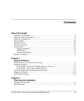
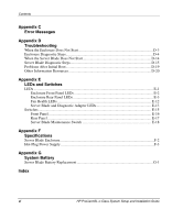
Contents E-1 Enclosure front panel LEDs E-2 E-2 Rear panel LEDS with interconnect switch E-3 E-3 Rear panel LEDs with RJ-21 patch panel E-6 E-4 Rear panel LEDs with RJ-45 patch panel E-9 E-5 Hot-plug fan health LEDs E-12 E-6 Server blade LEDs E-13 E-7 Diagnostic adapter LEDs E-13 E-8 Enclosure front panel buttons E-16 E-9 Enclosure rear panel buttons E-17 E-10 Server blade maintenance switches E-18 G-1 Locating and removing the battery on the server blade G-2 G-2 Installing the new battery G-3 List of Tables 2-1 ProLiant BL e-Class Standard Rack Mounting Hardware 2-8 2-2 Interconnect Tray Configurations 2-10 3-1 Interconnect Switch Connectors 3-16 3-2 RJ-21 Patch Panel Connectors 3-17 3-3 RJ-45 Patch Panel Connectors 3-18 3-4 Cable Pinout (Sample for Server Blades 1 through 10 NIC 1 3-22 3-5 Cable Pinout for a Null-Modem Cable 3-23 3-6 Connectors on the Diagnostic Adapter 3-36 4-1 ROM-Based Setup Utility Default Settings 4-5 4-2 Server Blade Event Messages 4-13 D-1 Enclosure Diagnostic Steps D-5 D-2 Is the Power LED on Both Power Supplies Solid Green D-5 D-3 Is the Fault LED on Both Power Supplies Off D-7 D-4 Is the Enclosure Power LED on the Rear Panel Green D-9 D-5 Is the Enclosure Health LED on the Front of the Enclosure On D-10 D-6 Is the Local Management Console Displaying Information When Connected to the Enclosure? ...D-11 D-7 Is the Integrated Administrator Health LED Green D-12 D-8 Is the Fan Health LED Green D-13 D-9 Server Blade Diagnostic Steps D-15 D-10 Is the Power LED on the Server Blade Green D-16 D-11 Is the Health LED on the Server Blade Green D-17 D-12 Is the NIC 1 or NIC 2 LED on the Server Blade Illuminated D-18 viii HP ProLiant BL e-Class System Setup and Installation Guide

  • 1
  • 2
  • 3
  • 4
  • 5
  • 6
  • 7
  • 8
  • 9
  • 10
  • 11
  • 12
  • 13
  • 14
  • 15
  • 16
  • 17
  • 18
  • 19
  • 20
  • 21
  • 22
  • 23
  • 24
  • 25
  • 26
  • 27
  • 28
  • 29
  • 30
  • 31
  • 32
  • 33
  • 34
  • 35
  • 36
  • 37
  • 38
  • 39
  • 40
  • 41
  • 42
  • 43
  • 44
  • 45
  • 46
  • 47
  • 48
  • 49
  • 50
  • 51
  • 52
  • 53
  • 54
  • 55
  • 56
  • 57
  • 58
  • 59
  • 60
  • 61
  • 62
  • 63
  • 64
  • 65
  • 66
  • 67
  • 68
  • 69
  • 70
  • 71
  • 72
  • 73
  • 74
  • 75
  • 76
  • 77
  • 78
  • 79
  • 80
  • 81
  • 82
  • 83
  • 84
  • 85
  • 86
  • 87
  • 88
  • 89
  • 90
  • 91
  • 92
  • 93
  • 94
  • 95
  • 96
  • 97
  • 98
  • 99
  • 100
  • 101
  • 102
  • 103
  • 104
  • 105
  • 106
  • 107
  • 108
  • 109
  • 110
  • 111
  • 112
  • 113
  • 114
  • 115
  • 116
  • 117
  • 118
  • 119
  • 120
  • 121
  • 122
  • 123
  • 124
  • 125
  • 126
  • 127
  • 128
  • 129
  • 130
  • 131
  • 132
  • 133
  • 134
  • 135
  • 136
  • 137
  • 138
  • 139
  • 140
  • 141
  • 142
  • 143
  • 144
  • 145
  • 146
  • 147
  • 148
  • 149
  • 150
  • 151
  • 152
  • 153
  • 154
  • 155
  • 156

Contents
E-1
Enclosure front panel LEDs
.....................................................................................
E-2
E-2
Rear panel LEDS with interconnect switch
..............................................................
E-3
E-3
Rear panel LEDs with RJ-21 patch panel
.................................................................
E-6
E-4
Rear panel LEDs with RJ-45 patch panel
.................................................................
E-9
E-5
Hot-plug fan health LEDs
......................................................................................
E-12
E-6
Server blade LEDs
.................................................................................................
E-13
E-7
Diagnostic adapter LEDs
........................................................................................
E-13
E-8
Enclosure front panel buttons
.................................................................................
E-16
E-9
Enclosure rear panel buttons
..................................................................................
E-17
E-10
Server blade maintenance switches
........................................................................
E-18
G-1
Locating and removing the battery on the server blade
...........................................
G-2
G-2
Installing the new battery
.........................................................................................
G-3
List of Tables
2-1
ProLiant BL e-Class Standard Rack Mounting Hardware
........................................
2-8
2-2
Interconnect Tray Configurations
...........................................................................
2-10
3-1
Interconnect Switch Connectors
..............................................................................
3-16
3-2
RJ-21 Patch Panel Connectors
................................................................................
3-17
3-3
RJ-45 Patch Panel Connectors
................................................................................
3-18
3-4
Cable Pinout (Sample for Server Blades 1 through 10 NIC 1)
...............................
3-22
3-5
Cable Pinout for a Null-Modem Cable
....................................................................
3-23
3-6
Connectors on the Diagnostic Adapter
....................................................................
3-36
4-1
ROM-Based Setup Utility Default Settings
..............................................................
4-5
4-2
Server Blade Event Messages
.................................................................................
4-13
D-1
Enclosure Diagnostic Steps
......................................................................................
D-5
D-2
Is the Power LED on Both Power Supplies Solid Green?
........................................
D-5
D-3
Is the Fault LED on Both Power Supplies Off?
.......................................................
D-7
D-4
Is the Enclosure Power LED on the Rear Panel Green?
...........................................
D-9
D-5
Is the Enclosure Health LED on the Front of the Enclosure On?
...........................
D-10
D-6
Is the Local Management Console Displaying Information When Connected
to the Enclosure?
....................................................................................................
D-11
D-7
Is the Integrated Administrator Health LED Green?
..............................................
D-12
D-8
Is the Fan Health LED Green?
...............................................................................
D-13
D-9
Server Blade Diagnostic Steps
...............................................................................
D-15
D-10
Is the Power LED on the Server Blade Green?
......................................................
D-16
D-11
Is the Health LED on the Server Blade Green?
......................................................
D-17
D-12
Is the NIC 1 or NIC 2 LED on the Server Blade Illuminated?
...............................
D-18
viii
HP ProLiant BL e-Class System Setup and Installation Guide