HP BL10e HP ProLiant BL e-Class System Setup and Installation Guide - Page 54
RJ-21 Patch Panel Connectors, Table 3-1, Interconnect Switch Connectors
 |
UPC - 808736933599
View all HP BL10e manuals
Add to My Manuals
Save this manual to your list of manuals |
Page 54 highlights
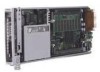
Installing and Cabling the System Table 3-1: Interconnect Switch Connectors Item Description Location 1 Gigabit Ethernet port 26 connector on switch B Interconnect switch 2 Gigabit Ethernet port 25 connector on switch B Interconnect switch 3 Integrated Administrator management connector (10/100 Ethernet)* Integrated Administrator module 4 Integrated Administrator console connector (serial)* Integrated Administrator module 5 Enclosure link (RJ-45) connector-Reserved* Integrated Administrator module 6 Enclosure link (RJ-45) connector-Reserved* Integrated Administrator module 7 Gigabit Ethernet port 26 connector on switch A Interconnect switch 8 Gigabit Ethernet port 25 connector on switch A Interconnect switch * These items denote connectors for the Integrated Administrator module. RJ-21 Patch Panel Connectors The RJ-21 patch panel features a simplified connector configuration that consolidates the server blade network connections into four RJ-21 connectors. Figure 3-14: RJ-21 patch panel connectors 3-16 HP ProLiant BL e-Class System Setup and Installation Guide
-
 1
1 -
2
-
3
-
4
-
5
-
6
-
7
-
8
-
9
-
10
-
11
-
12
-
13
-
14
-
15
-
16
-
17
-
18
-
19
-
20
-
21
-
22
-
23
-
24
-
25
-
26
-
27
-
28
-
29
-
30
-
31
-
32
-
33
-
34
-
35
-
36
-
37
-
38
-
39
-
40
-
41
-
42
-
43
-
44
-
45
-
46
-
47
-
48
-
 49
49 -
 50
50 -
 51
51 -
 52
52 -
 53
53 -
 54
54 -
 55
55 -
 56
56 -
 57
57 -
 58
58 -
 59
59 -
60
-
61
-
62
-
63
-
64
-
65
-
66
-
67
-
68
-
69
-
70
-
71
-
72
-
73
-
74
-
75
-
76
-
77
-
78
-
79
-
80
-
81
-
82
-
83
-
84
-
85
-
86
-
87
-
88
-
89
-
90
-
91
-
92
-
93
-
94
-
95
-
96
-
97
-
98
-
99
-
100
-
101
-
102
-
103
-
104
-
105
-
106
-
107
-
108
-
109
-
110
-
111
-
112
-
113
-
114
-
115
-
116
-
117
-
118
-
119
-
120
-
121
-
122
-
123
-
124
-
125
-
126
-
127
-
128
-
129
-
130
-
131
-
132
-
133
-
134
-
135
-
136
-
137
-
138
-
139
-
140
-
141
-
142
-
143
-
144
-
145
-
146
-
147
-
148
-
149
-
150
-
151
-
152
-
153
-
154
-
155
-
156
 |
 |
