HP BL10e HP ProLiant BL e-Class System Setup and Installation Guide - Page 41
Press the interconnect tray release buttons 1.
 |
UPC - 808736933599
View all HP BL10e manuals
Add to My Manuals
Save this manual to your list of manuals |
Page 41 highlights
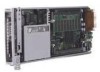
Installing and Cabling the System 5. Press the interconnect tray release buttons (1). 6. Pull the slate blue ejector levers toward the rear of the enclosure (2). NOTE: Slate blue indicates internal touch point components. Figure 3-2: Pulling the interconnect tray ejector levers HP ProLiant BL e-Class System Setup and Installation Guide 3-3
-
 1
1 -
2
-
3
-
4
-
5
-
6
-
7
-
8
-
9
-
10
-
11
-
12
-
13
-
14
-
15
-
16
-
17
-
18
-
19
-
20
-
21
-
22
-
23
-
24
-
25
-
26
-
27
-
28
-
29
-
30
-
31
-
32
-
33
-
34
-
35
-
 36
36 -
 37
37 -
 38
38 -
 39
39 -
 40
40 -
 41
41 -
 42
42 -
 43
43 -
 44
44 -
 45
45 -
 46
46 -
47
-
48
-
49
-
50
-
51
-
52
-
53
-
54
-
55
-
56
-
57
-
58
-
59
-
60
-
61
-
62
-
63
-
64
-
65
-
66
-
67
-
68
-
69
-
70
-
71
-
72
-
73
-
74
-
75
-
76
-
77
-
78
-
79
-
80
-
81
-
82
-
83
-
84
-
85
-
86
-
87
-
88
-
89
-
90
-
91
-
92
-
93
-
94
-
95
-
96
-
97
-
98
-
99
-
100
-
101
-
102
-
103
-
104
-
105
-
106
-
107
-
108
-
109
-
110
-
111
-
112
-
113
-
114
-
115
-
116
-
117
-
118
-
119
-
120
-
121
-
122
-
123
-
124
-
125
-
126
-
127
-
128
-
129
-
130
-
131
-
132
-
133
-
134
-
135
-
136
-
137
-
138
-
139
-
140
-
141
-
142
-
143
-
144
-
145
-
146
-
147
-
148
-
149
-
150
-
151
-
152
-
153
-
154
-
155
-
156
 |
 |

Installing and Cabling the System
5.
Press the interconnect tray release buttons (1).
6.
Pull the slate blue ejector levers toward the rear of the enclosure (2).
NOTE:
Slate blue indicates internal touch point components.
Figure 3-2:
Pulling the interconnect tray ejector levers
HP ProLiant BL e-Class System Setup and Installation Guide
3-3