HP Designjet 4500 HP Designjet 4500 Printer Series - Setup Poster - Page 4
anti-slip, DO NOT REMOVE - parts
 |
View all HP Designjet 4500 manuals
Add to My Manuals
Save this manual to your list of manuals |
Page 4 highlights
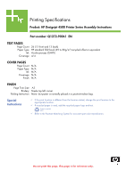
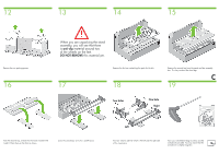
12 13 14 15 Remove the two packing pieces. 16 When you are unpacking the stand assembly, you will see that there is anti-slip material around two of the wheels on the feet. DO NOT REMOVE this material yet. Remove the first tray containing the parts for the bin. 17 18 Remove the second tray from the stand and bin assembly box. This tray contains the stand legs. C 19 Two holes One hole Right From the second tray, remove the two boxes marked with L and R. Place them on the floor as shown. Lower the cross-brace on to the L and R boxes. Left You now need to identify which is the left and the right side of the cross-brace. Now you will need the bag of screws and the screwdriver provided. You may notice that the screwdriver is slightly magnetic.
-
 1
1 -
 2
2 -
 3
3 -
 4
4 -
 5
5 -
 6
6 -
 7
7 -
 8
8 -
 9
9 -
 10
10 -
11
-
12
-
13
-
14
-
15
-
16
-
17
-
18
-
19
-
20
-
21
-
22
-
23
-
24
-
25
-
26
-
27
 |
 |

C
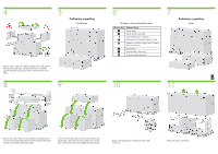
Remove the first tray containing the parts for the bin.
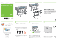
When you are unpacking the stand
assembly, you will see that there
is
anti-slip
material around two
of the wheels on the feet.
DO NOT REMOVE
this material yet.
From the second tray, remove the two boxes marked with
L and R. Place them on the floor as shown.
Remove the second tray from the stand and bin assembly
box. This tray contains the stand legs.
Lower the cross-brace on to the L and R boxes.
You now need to identify which is the left and the right side
of the cross-brace.
Now you will need the bag of screws and the
screwdriver provided. You may notice that the
screwdriver is slightly magnetic.
Two holes
Left
Right
One hole
Remove the two packing pieces.
13
12
14
15
17
16
18
19