HP Designjet 4500 HP Designjet 4500 Printer Series - Setup Poster - Page 6
Left leg, Right leg - help
 |
View all HP Designjet 4500 manuals
Add to My Manuals
Save this manual to your list of manuals |
Page 6 highlights
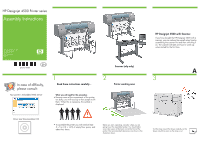
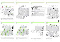
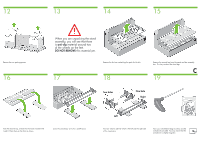
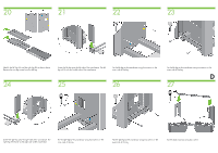
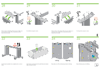
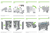
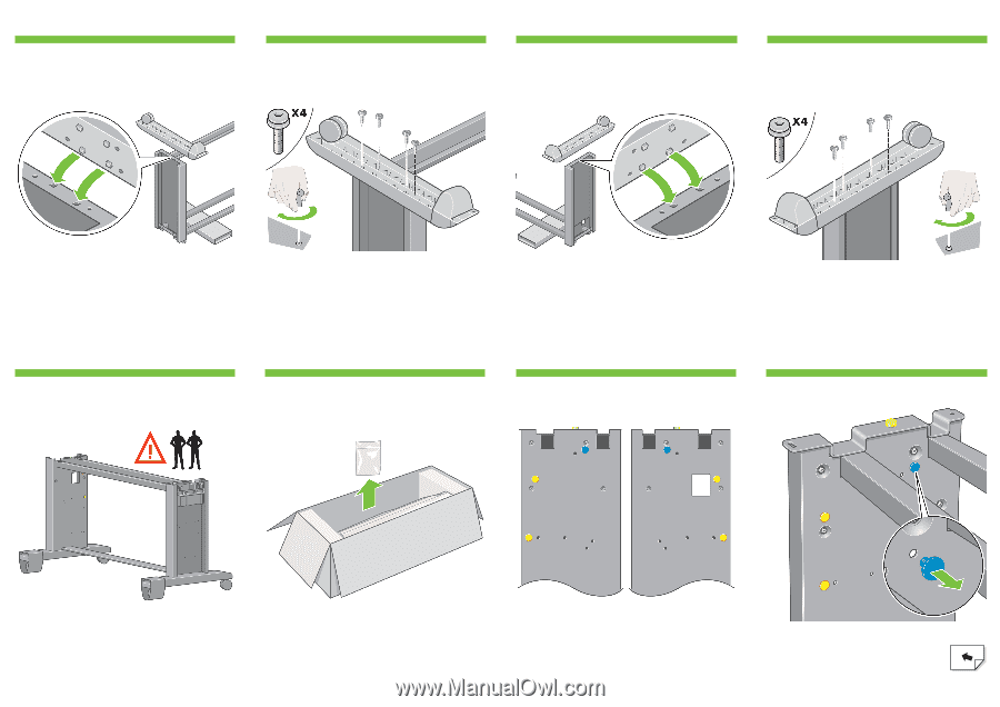
28 29 30 31 Position a foot on the left leg. There are pins to help you to position the foot correctly. Do not remove the anti-slip material from the wheel. Fix the left foot using four screws. 32 33 Position a foot on the right leg. There are pins to help you to position the foot correctly. Do not remove the anti-slip material from the wheel. Fix the right foot using four screws. E 34 35 Turn the stand assembly into an upright position as shown above. Open the box containing the roll module. Remove the plastic bag containing the screws. Left leg Right leg Please take note of the colored plugs located on the legs. Remove the blue plug on the left leg.
-
 1
1 -
 2
2 -
 3
3 -
 4
4 -
 5
5 -
 6
6 -
 7
7 -
 8
8 -
 9
9 -
 10
10 -
 11
11 -
 12
12 -
13
-
14
-
15
-
16
-
17
-
18
-
19
-
20
-
21
-
22
-
23
-
24
-
25
-
26
-
27
 |
 |
E
Fix the left foot using four screws.
Position a foot on the right leg. There are pins to help you to
position the foot correctly. Do not remove the anti-slip
material from the wheel.
Fix the right foot using four screws.
Turn the stand assembly into an upright position as shown
above.
Open the box containing the roll module. Remove the plastic
bag containing the screws.
Please take note of the colored plugs located on the legs.
Remove the blue plug on the left leg.
Left leg
Right leg
Position a foot on the left leg. There are pins to help you to
position the foot correctly. Do not remove the anti-slip
material from the wheel.
29
28
30
31
33
32
34
35