HP Model 715/100 hp 9000 series 700 model 715 workstations service handbook (a
HP Model 715/100 - Workstation Manual
 |
View all HP Model 715/100 manuals
Add to My Manuals
Save this manual to your list of manuals |
HP Model 715/100 manual content summary:
- HP Model 715/100 | hp 9000 series 700 model 715 workstations service handbook (a - Page 1
Service Handbook HP 9000 Series 700 Model 715 Workstations HP Part Number. A2600-90039 Click to go to the Table of Contents 3404 East Harmony Road, Fort Collins, CO. 80525 - HP Model 715/100 | hp 9000 series 700 model 715 workstations service handbook (a - Page 2
. HEWLETT-PACKARD MAKES NO WARRANTY OF ANY KIND WITH REGARD TO THIS MANUAL, INCLUDING, BUT NOT LIMITED TO, THE IMPLIED WARRANTIES OF MERCHANTABILITY AND and replacement parts can be obtained from your local Sales and Service Office. E Copyright Hewlett-Packard Company 1995 This document contains - HP Model 715/100 | hp 9000 series 700 model 715 workstations service handbook (a - Page 3
previous edition. Update packages may be issued between editions and contain replacement and additional pages to be merged into the manual by the user. The manual printing date and part number indicate its current edition. The printing date changes when a new edition is printed. (Minor corrections - HP Model 715/100 | hp 9000 series 700 model 715 workstations service handbook (a - Page 4
HP nodes and peripherals have been tested and comply with these limits. The FCC regulations also require that computing devices used in the U.S. display and, if not installed and used in accordance with the instruction manual, may cause harmful interference to radio communications. Operation of this - HP Model 715/100 | hp 9000 series 700 model 715 workstations service handbook (a - Page 5
Compliance Any third-party I/O device installed in HP system(s) must be in accordance with the requirements set forth in the preceding Emissions Regulations statements. In the event that a third-party noncompliant I/O device is installed, the customer assumes all responsibility and liability - HP Model 715/100 | hp 9000 series 700 model 715 workstations service handbook (a - Page 6
The CD ROM mass-storage system is certified as a Class-1 laser product under the U.S. Department of Health and Human services (DHHS) Radiation Performance Standard according to the Radiation Control for Health and Safety Act of 1968. This means that the mass-storage system does not produce hazardous - HP Model 715/100 | hp 9000 series 700 model 715 workstations service handbook (a - Page 7
Warnings and Cautions WARNING: Removing device cover may expose sharp edges in equipment chassis. To avoid injury, use care when installing customer add-on devices. WARNUNG: Das Entfernen der Geräteabdeckung legt die scharfen Kanten im Inneren des Gerätes frei. Um Verietzungen zu vermeiden, seien - HP Model 715/100 | hp 9000 series 700 model 715 workstations service handbook (a - Page 8
of Contents Product Information 1-1 Product Description 1-1 System Unit Controls and Front Panel Connectors 1-4 Understanding the LEDs 1-5 System Unit Rear Panel Connectors 1-7 SCSI Connector 1-9 HP Parallel I/O Connector 1-9 HP-HIL Connector 1-9 10-Pin Modular Jack 1-9 RS-232 - HP Model 715/100 | hp 9000 series 700 model 715 workstations service handbook (a - Page 9
Models 715/C, 715/33, 715/50, 715/75 3-17 Configuring the CRX Graphics Options 3-18 Setting Up a Single Monitor System 3-18 Setting Up a Dual Monitor System 3-21 Troubleshooting . . 5-21 Removing EISA Assembly Components (Retaining Clips) 5-24 Installing the EISA Assembly Components (End - HP Model 715/100 | hp 9000 series 700 model 715 workstations service handbook (a - Page 10
CRX and HCRX Graphics 5-35 Rear Audio Board 5-39 Memory 5-40 PCX-T Module (Model 715/75 5-42 Processor Board 5-45 System EEPROM 5-50 Calendar Battery 5-51 Diagrams 6-1 Reference 7-1 Service Notes 8-1 Index xi - HP Model 715/100 | hp 9000 series 700 model 715 workstations service handbook (a - Page 11
Figures Click on the page number to view a figure 1-1 System Unit Controls 1-4 1-2 Front Panel LEDs 1-5 1-3 System Unit Rear Panel Connectors 1-8 Graphics Configuration Switches 3-17 4-1 Front Panel LEDs 4-2 4-2 LED Display for CRX or HCRX Graphics Check 4-30 5-1 Illustrated Parts Breakdown - HP Model 715/100 | hp 9000 series 700 model 715 workstations service handbook (a - Page 12
Retainer Clips 5- 44 5-45 Removing the Processor Board 5-46 5-46 Component and Internal Connector Locations Model 715/C, 715/33, and 715/50 5-47 5-47 Component and Internal Connector Locations Model 715/64, 715/80, 715/100, 715/100XC . . 5-48 5-48 Component and Internal Connector Locations 715/75 - HP Model 715/100 | hp 9000 series 700 model 715 workstations service handbook (a - Page 13
6-1 6-2 System Unit Functional Block Diagram Model 715/C, 715/33, 715/50, and 715/75 6-3 6-3 System Unit Functional Block Diagram Model 715/64, 715/80, 715/100, and 715/100XC . 6-4 Tables Click on the page number to view a table 1-1 LED Display During Normal System Activity 1-6 1-2 Serial - HP Model 715/100 | hp 9000 series 700 model 715 workstations service handbook (a - Page 14
following versions of the HP-UX operating system: S Model 715/33, 715/50, and 715/C workstations use version 9.01 or later S Model 715/75 workstations use version 9.03 or later S Model 715/64, 715/80, 715/100, and 715/100XC workstations use version 9.05 or later The Model 715 workstations can house - HP Model 715/100 | hp 9000 series 700 model 715 workstations service handbook (a - Page 15
- Model 715/64 - Model 715/75 - Model 715/80 - Model 715/100 - Model 715/C - Model 715/100XC 8-192 MB 16-256 MB 32-256 MB 32-256 MB 32-256 MB 32-256 MB 32-256 MB 32-256 MB S Mass Storage - 1-GB SCSI hard disk drive (full height, 3.5-inch, Micropolis, DMD, DEC, and Seagate 1-GB drives are supported - HP Model 715/100 | hp 9000 series 700 model 715 workstations service handbook (a - Page 16
RS-232 Ports - One 25-pin HP parallel port - 8-bit, single-ended SCSI-2 interface - HP-HIL port (715/C, 715/33, 715/50, and 715/75 systems only) for HP-UX keyboards and other HP-HIL devices - Dual mini-DIN ports on the Keyboard Adapter Module (715/64, 715/80, and 715/100 Systems only) for AT-style - HP Model 715/100 | hp 9000 series 700 model 715 workstations service handbook (a - Page 17
Of Control) switches. Use the Power switch to power the system unit on and off. Use the TOC switch to reset the operating system. Do not push the TOC switch unless you have first shutdown the operating system by using the shutdown command. NOTICE: Model 715/64, 715/80, 715/100, and 715/100XC - HP Model 715/100 | hp 9000 series 700 model 715 workstations service handbook (a - Page 18
four amber LEDs (8, 7, 6, and 5), they also help you to troubleshoot the workstation by coming on in certain patterns during system failures (see Chapter LEDs Table 1-1 lists how the LEDs report during normal HP-UX system activity. The green Power LED remains lit while the system is powered - HP Model 715/100 | hp 9000 series 700 model 715 workstations service handbook (a - Page 19
Table 1-1. LED Display During Normal System Activity LED Display (1 Through 4 Flashing) 8 7 6 5 4 32 1 Meaning Operating System Running Disk Access In Progress Network Receive In Progress Network Transmit In Progress = LED On or Flashing 1-6 Product Information - HP Model 715/100 | hp 9000 series 700 model 715 workstations service handbook (a - Page 20
following connectors on the system unit's rear panel: S SCSI connector S HP parallel I/O connector S HP-HIL connector (Model 715/C, 715/33, 715/50, and 715/75 workstations) S 10-pin modular jack (Model 715/64, 715/80, 715/100, and 715/100XC workstations) S RS-232 serial input/output connectors S 802 - HP Model 715/100 | hp 9000 series 700 model 715 workstations service handbook (a - Page 21
HP Parallel Connector SCSI Connector Power Switch Transfer of Control (TOC) Switch Built-In Graphics Connector Graphics Configuration Switches* Optional Connector for EISA, CRX, or HCRX Graphics Audio Line OUT Connector *These switches are not present on Model 715/64, 715/80, 715/100, and 715 - HP Model 715/100 | hp 9000 series 700 model 715 workstations service handbook (a - Page 22
Modular Jack Model 715/64, 715/80, 715/100, and 715/100XC workstations are equipped with a 10-pin modular jack. A Keyboard Adapter Module attaches to this connector by means of a special cable shipped with the unit. The Keyboard Adapter Module includes two mini-DIN connectors and an HP-HIL connector - HP Model 715/100 | hp 9000 series 700 model 715 workstations service handbook (a - Page 23
Table 1-2. Serial I/O Pins Pin No. 1 2 3 4 5 6 7 8 9 Signal DCD RXD TXD DTR GND DSR RTS CTS RI Description Data Carrier Detect Receive Data Transmit Data Data Terminal Ready Ground Data Set Ready Request To Send Clear To Send Ring Indicator 802.3 Network Connector Figure 1-3 shows the location - HP Model 715/100 | hp 9000 series 700 model 715 workstations service handbook (a - Page 24
Connectors for EISA, and Optional Graphics The system has a slot for an optional EISA (Extended Industry Standard Architecture) board or an optional CRX , HCRX , VISUALIZE or CRX-48 graphics board. EISA The one-slot EISA I/O port is a superset of ISA (Industry Standard Architecture). It extends the - HP Model 715/100 | hp 9000 series 700 model 715 workstations service handbook (a - Page 25
the workstation's power cord into the power cord connector to provide ac power to the system. Audio Line In and Audio Line Out Connectors The Model 715 workstation has CD quality stereo audio input and output capability through external input and output connectors on the front and rear panels and an - HP Model 715/100 | hp 9000 series 700 model 715 workstations service handbook (a - Page 26
control adjusts the brightness of the display. S The Contrast control adjusts the light-to-dark and dark-to-light contrast of the display. S The Degauss control on its base. No degauss control exists on the 19-inch grayscale monitor. Refer to the manual that came with the monitor for detailed information - HP Model 715/100 | hp 9000 series 700 model 715 workstations service handbook (a - Page 27
AT-style keyboard that uses a mini-DIN, PS/2-style, connector, Model # A4030B) CAUTION: When connecting a HIL device (such as the ITF keyboard) ensure that the device conforms to the HP-HIL specification. Devices that are not HP-HIL compatible but have similar connectors may appear to be compatible - HP Model 715/100 | hp 9000 series 700 model 715 workstations service handbook (a - Page 28
blank1 (left) blank2 blank3 blank4 (right) Menu Stop Break / Reset Prev System / User Select Next Return Extend Char (left) Extend Char (right) Clear Line Clear Display Insert Line Delete Line Print / Enter , (number pad) Tab (number pad) (Continued) Product Information 1-15 - HP Model 715/100 | hp 9000 series 700 model 715 workstations service handbook (a - Page 29
Table 1-3. PC/AT Keyboard to ITF Keyboard Equivalent Keys (cont.) PC/AT Keycap Symbol Esc Insert Home Delete Caps Lock Esc Shifted Pause / Break Shifted Num Lock Shifted 0 / Ins (number pad) 1 / End (number pad) 2 / B (number pad) 3 / Pg Dn (number pad) 4 / A (number pad) 6 / " (number pad 7 / Home - HP Model 715/100 | hp 9000 series 700 model 715 workstations service handbook (a - Page 30
Models 715 Type Operating Temperature Non-Operating Temperature Humidity Operating Altitude Acoustic Noise Electrical Input Maximum Heat Dissipation Specification +5 to +40° C -40 to +70° C 15-80% maximum operating @ 40° C 3100 meters Sound Power Level (LWA) < 4.4 Bells to 30° C (diskless) 100 - HP Model 715/100 | hp 9000 series 700 model 715 workstations service handbook (a - Page 31
- ZH1/618 S CSA C22.2-950M Installation Refer to the following manuals for system installation information: S HP 9000 Series 700 Model 715 Hardware Installation Guide (Part Number A2084-90628) S HP 9000 Series 700 Model 715 Owner's Guide (Part Number A2084-90629) Preventive Maintenance There is no - HP Model 715/100 | hp 9000 series 700 model 715 workstations service handbook (a - Page 32
setting up and changing the system configuration. Workstation and System Unit Configurations Refer to the HP 9000 Series 700 Configuration Guide for a complete list of supported accessories, peripherals, and operating systems. FRU Configurations This section provides information for setting up or - HP Model 715/100 | hp 9000 series 700 model 715 workstations service handbook (a - Page 33
-MB CD-ROM (ID No. 2) External SCSI HP Standalone Magneto-Optical Drive (C1701A) (ID No. 0) CD-ROM Drive (A1999A) (ID No. 2) 20-GB Magneto-Optical Autochanger (C1700A) 1st (ID No. 3) 2nd (ID No. 4) 3rd (ID No. 5) *Model 715/64, 715/80, 715/100, and 715/100XC workstations have a PC- style floppy and - HP Model 715/100 | hp 9000 series 700 model 715 workstations service handbook (a - Page 34
NOTICE: A0, A1, and A2 are the SCSI ID jumpers. The jumpers TE, SS, WS, and I/O should be removed, and the jumper EP and INT should be in place. LED SCSI ID 6 SCSI ID 5 I/O INT (1 GB only) SS TE EP WS A0 (LSB) A1 A2 (MSB) Figure 3-2. Quantum 525-MB and 1-GB Disk Drive Jumpers Configuration 3-3 - HP Model 715/100 | hp 9000 series 700 model 715 workstations service handbook (a - Page 35
SCSI ID 1 2 3 4 5 6 7 8 9 10 6 5 4 3 2 1 0 No Jumper Figure 3-3. Quantum 1-GB and 2-GB Low Profile Disk Drive Jumpers 3-4 Configuration - HP Model 715/100 | hp 9000 series 700 model 715 workstations service handbook (a - Page 36
LED Front View 1 - Write Protect 2 - Unit Attention 3 - SDTR 4 - Parity Enable 5 - Auto Spin-Up 6 - Sync Spindle 7 - Sync Spindle (First Drive) SCSI ID 6 1 2 3 4 5 6 7 8 9 10 (Second Drive) SCSI ID 5 1 2 3 4 5 6 7 8 9 10 Front NOTICE: The last three jumpers (8, 9, and 10) are the SCSI ID - HP Model 715/100 | hp 9000 series 700 model 715 workstations service handbook (a - Page 37
Terminator Resistor Modules (Must be removed) Terminator Power Parity Enable Configuration NOTICE: (First Drive) SCSI ID 6 1 234 5 6 (Second Drive) SCSI ID 5 1 234 5 6 The first three jumpers (1, 2, and 3) should be removed. The SCSI ID jumpers are jumpers 4, 5, and 6. Figure 3-5. Seagate 525-MB - HP Model 715/100 | hp 9000 series 700 model 715 workstations service handbook (a - Page 38
Terminator Resistor Modules (Must be removed) Factory-Installed Jumpers (Do not remove) (First Drive) SCSI ID 6 ID 0 ID 1 ID 2 PARITY WPROT SPIN 0 SPIN 1 (Second Drive) SCSI ID 5 ID 0 ID 1 ID 2 PARITY WPROT SPIN 0 SPIN 1 NOTICE: ID 0, ID 1, and ID 2 are the SCSI ID jumpers. The jumpers PARITY, - HP Model 715/100 | hp 9000 series 700 model 715 workstations service handbook (a - Page 39
LED NOTICE: A0, A1, and A2 are the SCSI ID jumpers. SCSI SCSI ID 5 ID 6 Sync Spindle Parity Enable Write Protect A2 A1 A0 SCSI Terminators (Must be removed) Figure 3-7. Quantum 210-MB and 425-MB Winchester Drive Jumpers (Models ProDrive 210S and ProDrive 425S) 3-8 Configuration - HP Model 715/100 | hp 9000 series 700 model 715 workstations service handbook (a - Page 40
LED Front View J3 J3 SCSI ID 5 1 2 3 4 5 6 7 8 9 10 Termination Header NOTICE: The first three jumpers (1, 2, and 3) are the SCSI ID jumpers. Only jumpers 1, 3, and 7 should be in place. All other jumpers should be removed. Back Bottom View J3 NOTICE: Remove all jumpers. Figure 3-8. DEC 1-GB - HP Model 715/100 | hp 9000 series 700 model 715 workstations service handbook (a - Page 41
7 A2 6 Synch Spindle 5 Synch Spindle 4 Auto Spin Up 3 Parity 2 SDTR 1 Unit Attention SCSI Terminator Jumpers (New Board) Figure 3-9. Hewlett-Packard 420-MB Winchester Drive Jumpers (Model C2235) 3-10 Configuration - HP Model 715/100 | hp 9000 series 700 model 715 workstations service handbook (a - Page 42
SCSI ID 6 5 4 3 2 1 0 1 GB is Model HPC3324A 2 GB is Model HPC3325A Figure 3-10. Hewlett-Packard 1-GB and 2-GB Low Profile Drive Jumpers Configuration 3-11 - HP Model 715/100 | hp 9000 series 700 model 715 workstations service handbook (a - Page 43
Top of Floppy Disk Drive SCSI ID Address Jumpers ID 2 ID 1 Jumper in = 0; out = 1 ID 0 Terminator Resistor Modules (Must be removed) Target ID 0 1 23 4 56 ID2 Jumpers ID1 ID0 (Default) Figure 3-11. SCSI Floppy Drive Address Jumper Settings 3-12 Configuration - HP Model 715/100 | hp 9000 series 700 model 715 workstations service handbook (a - Page 44
XM-3201B SCSI Address Switches Target ID 0 1 (Default) 2 3 Address Settings SCSI Terminators (must be removed) Target ID 4 5 6 Address Settings Model XM-3301B Target ID 0 Jumpers 1 2 (Default) 3 Target ID 4 5 6 Jumpers Figure 3-12. CD-ROM SCSI Address Jumper Settings Configuration 3-13 - HP Model 715/100 | hp 9000 series 700 model 715 workstations service handbook (a - Page 45
SCSI Terminators (must be removed) Target Term ID PWR 0 Jumpers Target Term ID2 ID1 ID0 ID PWR 4 Jumpers ID2 ID1 ID0 1 5 2 6 3 (Default) Figure 3-13. DDS SCSI Address Jumper Settings (Model C1504C) 3-14 Configuration - HP Model 715/100 | hp 9000 series 700 model 715 workstations service handbook (a - Page 46
Installing Additional Memory Figure 3-14 shows the location of the memory boards within the system unit. Memory Boards Figure 3-14. Memory SIMM Locations Configuration 3-15 - HP Model 715/100 | hp 9000 series 700 model 715 workstations service handbook (a - Page 47
r c15E1GG1 c15E1GG i.C sG A sR 1 E C r c15ERR -c15Ei1 c15E5G1 c15EaS1 c15Ec51 c15EhG1 sG s Cp Co Pair 1C prr 2 r c15ERR1 1 Pair 0 i 5C Right Side of System Unit A B Pair 3 A B Pair 2 A B Pair 1 A B Pair 0 Front of System Unit Figure 3-15. Memory Connector Configuration 3-16 - HP Model 715/100 | hp 9000 series 700 model 715 workstations service handbook (a - Page 48
Changing the Built-In Graphics Configuration Switches (Models 715/C, 715/33, 715/50, 715/75) Figure 3-16 shows the built-in graphics configuration switch settings. Set the switches according to the type of monitor that is connected to the system - HP Model 715/100 | hp 9000 series 700 model 715 workstations service handbook (a - Page 49
HP-UX, and after a few minutes, there is no output on the monitor, use the following procedures to configure the workstation: 1. Power off the workstation. 2. Connect the monitor to the built-in graphics connector as shown in Chapter 1 of this manual. 3. For Model 715/C, 715/33, 715/50, and 715/75 - HP Model 715/100 | hp 9000 series 700 model 715 workstations service handbook (a - Page 50
the following command: /etc/reboot Return 10. The system shuts down and starts to reboot. Press and hold Esc when the following message is displayed: Selecting a system to boot. To stop selection process press and hold the ESCAPE key. In a few seconds, the following message appears: Terminating - HP Model 715/100 | hp 9000 series 700 model 715 workstations service handbook (a - Page 51
is now searching for devices that may hold file systems from which it can boot HP-UX. As they are found, they appear in a list similar to the following monitor to the CRX graphics connector as shown in Chapter 1 of this manual. 16. Power on the monitor and the workstation. 3-20 Configuration - HP Model 715/100 | hp 9000 series 700 model 715 workstations service handbook (a - Page 52
optional graphics (CRX) and the built-in graphics. The CRX graphics is set up as the default display and console device and the built-in graphics is set up as the secondary display device. NOTICES: Dual monitors are supported only with the CRX-24 graphics options. Only the 20-inch color monitors are - HP Model 715/100 | hp 9000 series 700 model 715 workstations service handbook (a - Page 53
following command: /etc/reboot Return 13. The system shuts down and starts to reboot. Press and hold Esc when the following message is displayed: Selecting a system to boot. To stop selection process press and hold the ESCAPE key. In a few seconds, the following message appears: Selection process - HP Model 715/100 | hp 9000 series 700 model 715 workstations service handbook (a - Page 54
searching for devices that may hold file systems from which it can boot HP-UX. As they are found, they appear in a list similar manual. Connect the second monitor to the built-in graphics connector on the rear of the workstation, as shown in Chapter 1. For Model 715/C, 715/33, 715/50, and 715/75 - HP Model 715/100 | hp 9000 series 700 model 715 workstations service handbook (a - Page 55
a problem, run the ISL diagnostics and the SupportWave online tests. Refer to the following sections for more information about Self Test. For a complete description on using ISL diagnostics and SupportWave, see the Precision Architecture RISC HP 9000 Series 700 Diagnostics Manual. Troubleshooting - HP Model 715/100 | hp 9000 series 700 model 715 workstations service handbook (a - Page 56
display of Model 715/C, 715/33, 715/50, and 715/75 HP-UX kernel error codes. Table 4-5 shows the LED error codes as they appear on the front panel display of Model 715/64, 715/80, , 715/100, and 715/100XC workstations. Use these LED codes to determine the failing component. 4-2 Troubleshooting - HP Model 715/100 | hp 9000 series 700 model 715 workstations service handbook (a - Page 57
Model 715/C, 715/33, 715/50, and 715/75 Self Test LED Error Codes LED Display 8 7 654 3 2 1 Error Message CPU Error - Model 715/33 and 50. PCX-T FRU Error - Model 715/75. CPU Error - Model 715/33 and 50. PCX-T FRU Error - Model 715/75. CPU Error - Model 715/33 and 50 Motherboard Error - 715/75 - HP Model 715/100 | hp 9000 series 700 model 715 workstations service handbook (a - Page 58
Table 4-1. Model 715/C, 715/33, 715/50, and 715/75 Self Test LED Error Codes (Cont.) LED Display Error Message 8 7 654 32 1 Memory Pair1, Slot B Error. Memory Pair 1, Slot A Error. Memory Pair 2, Slot to access Graphical Console Device. = LED On or Flashing (Continued) 4-4 Troubleshooting - HP Model 715/100 | hp 9000 series 700 model 715 workstations service handbook (a - Page 59
Table 4-1. Model 715/C, 715/33, 715/50, and 715/75 Self Test LED Error Codes (Cont.) LED Display 8 7 6 543 2 1 Error Message Unable to initialize EISA Slot. Error on SGC Slot 1 (Built-in Graphics) Error on SGC Slot 2 (Optional Graphics) = LED On or Flashing Troubleshooting 4-5 - HP Model 715/100 | hp 9000 series 700 model 715 workstations service handbook (a - Page 60
Table 4-2. Model 715/C, 715/33, 715/50, and 715/75 PDC LED Codes LED Display 8 765 432 1 Status Destructive Memory init. Subsystem Init. Setting Up Default EISA config. At least one Selftest failed (Service Mode). Error reading EEPROM or Invalid Stable Storage. Unexpected interrupt. No Console - HP Model 715/100 | hp 9000 series 700 model 715 workstations service handbook (a - Page 61
Table 4-2. Model 715/C, 715/33, 715/50, and 715/75 PDC LED Codes (Cont.) LED Display 8 765 432 1 Status HPMC Handling initiated. HPMC due to Cache Error. HPMC due to Memory Speed sensing. Illegal Processor Speed/Clock Ratio sensing. Bad Memory Hardware. = LED On or Flashing Troubleshooting 4-7 - HP Model 715/100 | hp 9000 series 700 model 715 workstations service handbook (a - Page 62
Table 4-3. Model 715/C, 715/33, 715/50, and 715/75 ISL LED Codes LED Display 8 765 432 1 Status ISL executing. ISL is autobooting from the Autoexec File. ISL cannot find Utility into Memory. Incorrect Checksum: Reading Utility into Memory. = LED On or Flashing (Continued) 4-8 Troubleshooting - HP Model 715/100 | hp 9000 series 700 model 715 workstations service handbook (a - Page 63
Table 4-3. Model 715/C, 715/33, 715/50, and 715/75 ISL LED Codes (Cont.) LED Display 8 765 432 1 Status System Console needed. Internal inconsistency: Invalid Boot Device Class. Destination File Header inconsistent: Bad aux_id. Bad Utility File Type. = LED On or Flashing Troubleshooting 4-9 - HP Model 715/100 | hp 9000 series 700 model 715 workstations service handbook (a - Page 64
Table 4-4. Model 715/C, 715/33, 715/50, and 715/75 HP-UX Kernel LED Codes LED Display 8 765 432 1 Status Kernel loaded and Initialization begun. Kernel has entered main(). Kernel is Shutdown in process. TOC Dump. HPMC Dump. Operating System executing with Load Indicator X. 4-10 Troubleshooting - HP Model 715/100 | hp 9000 series 700 model 715 workstations service handbook (a - Page 65
Table 4-5. Model 715/64, 715/80, , 715/100, and 715/100XC LED Error Codes LED Display 8 765 43 2 1 Status CPU Error Fatal Error RAM Test Error Cache Error FP Co-processor Error Initialization Error No working console found, unable to boot = LED On or Flashing (Continued) Troubleshooting 4-11 - HP Model 715/100 | hp 9000 series 700 model 715 workstations service handbook (a - Page 66
Table 4-5. Model 715/64, 715/80, , 715/100, and 715/100XC LED Error Codes (Cont.) LED Display 8 765 43 2 1 = LED On or Flashing Status No bootable device found Memory Error Initialization Error 4-12 Troubleshooting - HP Model 715/100 | hp 9000 series 700 model 715 workstations service handbook (a - Page 67
to boot from the disk (or another boot device) by selecting it manually. To boot a device manually, follow these steps: 1. Turn off the power to the workstation, for devices that may hold file systems from which it can boot HP-UX. As they are found, they appear in a list, similar Troubleshooting 4-13 - HP Model 715/100 | hp 9000 series 700 model 715 workstations service handbook (a - Page 68
alternate boot path or any specified path using the BOOT command. S Set or display the real-time clock value using the DATE command (this command is not supported on Model 715/64, 715/80, , 715/100, and 715/100XC workstations). S Return to previous menu using the EXIT command. 4-14 Troubleshooting - HP Model 715/100 | hp 9000 series 700 model 715 workstations service handbook (a - Page 69
this command is not supported on Model 715/64, 715/80, , 715/100, and 715/100XC workstations). Syntax checking is performed for any supported commands. Error status is displayed on the console along the boot flags, HPMC error information, and operating system initialization data. Troubleshooting 4-15 - HP Model 715/100 | hp 9000 series 700 model 715 workstations service handbook (a - Page 70
Boot Command Notations The BOOT command supports the following three notations: S Mnemonic S PA-RISC I/O S S BOOT P1 Return attempts to boot from the second path indicated by the SEARCH command. Supported Boot Paths SCSI devices are bootable when connected to the SCSI port on the System card. - HP Model 715/100 | hp 9000 series 700 model 715 workstations service handbook (a - Page 71
Run off-line diagnostic programs (TDIAG, EISADIAG, and IOMAP). S Provide automatic booting of the HP-UX O/S after power-on or reset. The ISL program provides a standalone environment for loading Administration mode x) Exit and continue boot sequence ?) Help Select from menu: Troubleshooting 4-17 - HP Model 715/100 | hp 9000 series 700 model 715 workstations service handbook (a - Page 72
525 MB Quantum disk. The following messages, the ISL banner, and the ISL prompt are displayed: Trying scsi.6.0 Boot path initialized. Attempting to load IPL. Hard booted. ISL Revision A.00 Type hpux boot disc(;0)/hp-ux Return to load the HP-UX environment from the SCSI device. 4-18 Troubleshooting - HP Model 715/100 | hp 9000 series 700 model 715 workstations service handbook (a - Page 73
191. S listautofl or lsautofl - lists the contents of the (HP-UX) autoboot file. S support - boots the Support Tape from the boot device. S readss - displays 4 bytes (one word) from Stable Storage. The readss command number 46081-61601) to the audio input and audio connectors. Troubleshooting 4-19 - HP Model 715/100 | hp 9000 series 700 model 715 workstations service handbook (a - Page 74
> prompt to invoke the IOMAP test from the LIF area on the system disk. The IOMAP test will list the devices in the system. 4-20 Troubleshooting - HP Model 715/100 | hp 9000 series 700 model 715 workstations service handbook (a - Page 75
window; if you are using HP-VUE as your interface, you can also access the Support Tools Manager through the sys_admin directory. Three interfaces are available with the Support Tools Manager: a command- verify the system operation, type the following: CSTM> verify all Return Troubleshooting 4-21 - HP Model 715/100 | hp 9000 series 700 model 715 workstations service handbook (a - Page 76
or overlaid in any way. NOTE: If a VUE login screen is currently displayed on the monitor, the test will wait until someone logs in the HP VUE on the graphics monitor to release the lock. The test stops if : CSTM> exit Return If any tests fail, further diagnosis is necessary. 4-22 Troubleshooting - HP Model 715/100 | hp 9000 series 700 model 715 workstations service handbook (a - Page 77
BOOT PATH > ISL MODE > HP-UX MODE When the hardware detects an unrecoverable (HPMC) error in the HP-UX environment, an error message, referred to as an HP-UX Kernel Tombstone is displayed on the monitor. The state of with those shown in Table 4-6 and take the appropriate action. Troubleshooting 4-23 - HP Model 715/100 | hp 9000 series 700 model 715 workstations service handbook (a - Page 78
more than one failed FRU is identified, run the appropriate diagnostics to isolate the failed FRU. Note 2 For the Model 715/75, replace the PCX-T module. For other models, replace the Motherboard. See HPMC Caused by a Data Cache Parity Error for more information. Note 3 While Architected Main - HP Model 715/100 | hp 9000 series 700 model 715 workstations service handbook (a - Page 79
System Responder Address System Requester Address System Controller Status Value 0x20000000 0x9e000004 0x00000000 0x00000000 error was detected by logic in the memory module. Ignore the value in the System Controller Status word. The System Responder contains the SPA of the faulty SIMM pair. To - HP Model 715/100 | hp 9000 series 700 model 715 workstations service handbook (a - Page 80
- 0x0DFFFFFF 0x0E000000 - 0x0EFFFFFF 0x0F000000 - 0x0FFFFFFF For example, if the system configuration is: Pair 3: Pair 2 Pair 1: Pair 0: 32 MB SIMMs = 64 MB total for pair 16 MB SIMMS = 32 MB total for pair 32 MB SIMMs = 64 MB total for pair 8 MB SIMMs = 16 MB total for pair 4-26 Troubleshooting - HP Model 715/100 | hp 9000 series 700 model 715 workstations service handbook (a - Page 81
Range Size (MB) 0-8 8-16 16-24 24-32 32-40 40-48 48-56 56-64 64-72 72-80 80-88 88-96 96-104 104-112 112-120 120-128 128-136 136 0x0B000000 - 0x0B7FFFFF 0x0B800000 - 0x0BFFFFFF 0x0C000000 - 0x0CFFFFFF 0x0D000000 - 0x0DFFFFFF 0x0E000000 - 0x0EFFFFFF 0x0F000000 - 0x0FFFFFFF Troubleshooting 4-27 - HP Model 715/100 | hp 9000 series 700 model 715 workstations service handbook (a - Page 82
on the LEDs replace the faulty SIMM, otherwise, replace the SIMM pair identified in this procedure. Return the system state (e.g., FASTBOOT) to original condition. 4-28 Troubleshooting - HP Model 715/100 | hp 9000 series 700 model 715 workstations service handbook (a - Page 83
is forced when a data parity error is detected during a Load instruction to the memory address space or during a data cache flush operation. in the System Controller Status word. For Model 715/75, replace the PCX-T module. For any other Model 715, replace the Motherboard. Troubleshooting 4-29 - HP Model 715/100 | hp 9000 series 700 model 715 workstations service handbook (a - Page 84
a Model 715/C, 715/33, 715/50, or 715/75, check the workstation's graphics configuration switches, as shown in Chapter 3 of this manual, to ensure that the graphics switches are set correctly for the monitor. 7. Power on the monitor and the workstation. Observe the LED codes as they are displayed on - HP Model 715/100 | hp 9000 series 700 model 715 workstations service handbook (a - Page 85
"Configuring the CRX or HCRX Graphics Options" section in Chapter 3 of this manual to check that the system is properly set up for the optional graphics. 11 you still have nothing displayed on the monitor, the CRX or HCRX graphics option board is defective and must be replaced. Troubleshooting 4-31 - HP Model 715/100 | hp 9000 series 700 model 715 workstations service handbook (a - Page 86
and that all screws are properly seated. Refer to Figure 5-1 for an illustrated parts breakdown of the system unit. Table 5-1 lists all the FRUs for Model 715 systems. Table 5-2 lists some of the available EISA interface options. Field Replaceable Units 5-1 - HP Model 715/100 | hp 9000 series 700 model 715 workstations service handbook (a - Page 87
4 3 2 6 7 Shaded circles represent exchange parts. 1 8 9 10 11 12 13 14 15 17 16 Figure 5-1. Illustrated Parts Breakdown 5-2 Field Replaceable Units - HP Model 715/100 | hp 9000 series 700 model 715 workstations service handbook (a - Page 88
Board Model 715/64 e A2084-69014 Motherboard Model 715/75 e A4022-69518 Processor Board Model 715/80 e A2084-69017 Motherboard Model 715/C e A4022-69510 Processor Board Model 715/100 e A4022-69515 Processor Board Model 715/100XC e A2335-69222 PCX-T Module Model 715/75 e 8 98236 - HP Model 715/100 | hp 9000 series 700 model 715 workstations service handbook (a - Page 89
(mini-DIN) n * 46021-60201 Keyboard, HP-UX n * 46060-60202 Mouse (HP-HIL) n * A2839A Mouse (mini-DIN) Adapter n * A2084-40059 Floppy Bezel Insert Model 715/75 n * A2084-62004 SCSI Ribbon Cable n * A2084-00023 EMI Clip n * = not shown in Figure 5-1. Shaded boxes indicate the part is - HP Model 715/100 | hp 9000 series 700 model 715 workstations service handbook (a - Page 90
Grayscale Video Cable n * A2084-84005 Model 715/33 Logo Label n * A2084-84006 Model 715/50 Logo Label n * A2084-84007 Model 715/75 Logo Label n * A4022-84001 Model 715/64 Logo Label n * A4022-84005 Model 715/80 Logo Label n * A4022-84004 Model 715/100 Logo Label n * = not shown in - HP Model 715/100 | hp 9000 series 700 model 715 workstations service handbook (a - Page 91
External Graphics Processor Disconnect and remove the external graphics processor unit (if installed). If your workstation is installed in the deskside (standing) configuration, lift the rear of the system unit slightly while sliding the processor back, as shown in Figure 5-2. Figure 5-2. Removing - HP Model 715/100 | hp 9000 series 700 model 715 workstations service handbook (a - Page 92
Floor Stand Place the system unit on a flat surface, such as a table top, with the floor stand hanging over the edge. Slide the latch on the bottom of the floor stand to unlock it. Á Figure 5-3. Unlocking the Floor Stand Swing the end of the floor stand away from the system unit and remove it as - HP Model 715/100 | hp 9000 series 700 model 715 workstations service handbook (a - Page 93
Opening the System Unit Before opening the system unit, remove the floor stand. If a sticker is covering the handle, remove it. Slide the handle latch to the open position and carefully lift the top cover to fully open the system unit, as shown in Figure 5-5. Figure 5-5. Opening the System Unit - HP Model 715/100 | hp 9000 series 700 model 715 workstations service handbook (a - Page 94
Disk Drives Before removing the disk drives, perform the following steps: S Remove the optional external graphics processor (if installed). S Remove the floor stand. S Open the system unit. Disconnect the power cable and the SCSI cable from the disk drive. For CD-ROM drives, disconnect the CD-ROM - HP Model 715/100 | hp 9000 series 700 model 715 workstations service handbook (a - Page 95
Figure 5-7. Removing the Second Hard Disk Drive 5-10 Field Replaceable Units - HP Model 715/100 | hp 9000 series 700 model 715 workstations service handbook (a - Page 96
Figure 5-8. Removing the Floppy, CD-ROM, or DDS Drive Field Replaceable Units 5-11 - HP Model 715/100 | hp 9000 series 700 model 715 workstations service handbook (a - Page 97
Figure 5-9. Removing the Drive Brackets 5-12 Field Replaceable Units - HP Model 715/100 | hp 9000 series 700 model 715 workstations service handbook (a - Page 98
P8 (see Figure 5-12) Disk 3: CD-ROM or DDS Drive Power Connectors Disk 1: Winchester Drive Red Line Figure 5-10. SCSI and PC Floppy Cable Connections (Model 715/64, 715/80, and 715/100) Field Replaceable Units 5-13 - HP Model 715/100 | hp 9000 series 700 model 715 workstations service handbook (a - Page 99
Disk 1: Winchester Drive Disk 2: Winchester Drive Disk 3: Floppy Drive* Red Line To Processor Board Connector P8 (see the following figure) Power Connectors Disk 3: CD-ROM or DDS Drive Disk 1: Winchester Drive Red Line Figure 5-11. SCSI Cable Connections 5-14 Field Replaceable Units - HP Model 715/100 | hp 9000 series 700 model 715 workstations service handbook (a - Page 100
Processor Board Connector P8 Red Line Figure 5-12. Connecting SCSI Cable to Processor Board To Connector P5 on CPU Board CD-ROM Audio Cable Figure 5-13. CD-ROM Audio Cable Field Replaceable Units 5-15 - HP Model 715/100 | hp 9000 series 700 model 715 workstations service handbook (a - Page 101
Connect cable here Red Line Red Line Figure 5-14. Connecting the PC-Style Floppy Drive Ribbon Cable (Model 715/64, 715/80, and 715/100 Systems) 5-16 Field Replaceable Units - HP Model 715/100 | hp 9000 series 700 model 715 workstations service handbook (a - Page 102
Power Supply Before removing the power supply, perform the following steps: S Remove the optional external graphics processor (if installed). S Remove the floor stand. S Open the system unit. Remove the two screws that secure the power supply to the chassis. Disconnect the processor board cable and - HP Model 715/100 | hp 9000 series 700 model 715 workstations service handbook (a - Page 103
Front Audio Board Assembly Before removing a front audio board assembly, perform the following steps: S Remove the optional graphics processor (if installed). S Remove the floor stand. S Open the system unit. Unplug the bezel assembly cable from connector P2 on the CPU board. Use a flatblade - HP Model 715/100 | hp 9000 series 700 model 715 workstations service handbook (a - Page 104
Front Bezel Cover Plate Assembly To remove the blank cover plate, depress the snap tab on one end of the blank cover plate to remove the metal liner. Then press on the blank cover plate until it pops out of the system unit, as shown in Figure 5-17. Discard the metal liner plate and the blank cover - HP Model 715/100 | hp 9000 series 700 model 715 workstations service handbook (a - Page 105
the following steps: S Remove the floor stand. S Open the system unit. Use Figure 5-18 to determine if your system uses an End Cap or Retaining Clips to secure the EISA option, then proceed to the appropriate subsection for removing or installing the EISA option. EISA Option With End Cap End Cap - HP Model 715/100 | hp 9000 series 700 model 715 workstations service handbook (a - Page 106
Removing the EISA Assembly Components (End Cap) Remove each EISA assembly component as shown in the following sequence of illustrations until you have removed the component that you want to replace. Pinch the sides of the end cap and slide it away from the EISA board as shown in Figure 5-19. Figure - HP Model 715/100 | hp 9000 series 700 model 715 workstations service handbook (a - Page 107
Disconnect the EISA board from the EISA adapter board, as shown in Figure 5-20. EISA Board Adapter Board Figure 5-20. Disconnecting the EISA Board from the Adapter Board Use a Phillips screwdriver to unscrew the connector bracket from the connector bucket. Then remove the EISA board's connector - HP Model 715/100 | hp 9000 series 700 model 715 workstations service handbook (a - Page 108
Pinch the sides of the end cap and slide it from between the brackets as shown in Figure 5-22. Figure 5-22. Removing the End Cap Field Replaceable Units 5-23 - HP Model 715/100 | hp 9000 series 700 model 715 workstations service handbook (a - Page 109
Removing the EISA Assembly Components (Retaining Clips) Push the retaining clips away from the EISA board to release it. See Figure 5-23. Retaining Clips Retaining Clips Figure 5-23. Unsecuring the EISA Board 5-24 Field Replaceable Units - HP Model 715/100 | hp 9000 series 700 model 715 workstations service handbook (a - Page 110
Press the locking tab on the top of each standoff and lift the EISA assembly evenly from both sides until it is disengaged from the connector. Figure 5-24. Removing the EISA Assembly (Retainer Clips) Field Replaceable Units 5-25 - HP Model 715/100 | hp 9000 series 700 model 715 workstations service handbook (a - Page 111
Disconnect the EISA board from the EISA adapter board, as shown in Figure 5-20. EISA Board Adapter Board Figure 5-25. Disconnecting the EISA Board from the Adapter Board Use a Phillips screwdriver to unscrew the connector bracket from the connector bucket. Then remove the EISA board's connector - HP Model 715/100 | hp 9000 series 700 model 715 workstations service handbook (a - Page 112
Installing the EISA Assembly Components (End Cap) Perform the appropriate steps in this subsection to install the EISA assembly components that you removed. Skip those steps that don't apply. Pinch the sides of the end cap and slide it between the rails to the rear of the system unit (see Figure 5- - HP Model 715/100 | hp 9000 series 700 model 715 workstations service handbook (a - Page 113
Insert the connector bracket into the bucket, and then use a Phillips screwdriver to tighten the screw. Figure 5-28. Installing the Connector Bucket 5-28 Field Replaceable Units - HP Model 715/100 | hp 9000 series 700 model 715 workstations service handbook (a - Page 114
Insert the EISA board into the connector on the adapter board. Push firmly to ensure a secure connection. Refer to Figure 5-29. EISA Board Adapter Board Figure 5-29. Connecting the EISA Board to the Adapter Board Field Replaceable Units 5-29 - HP Model 715/100 | hp 9000 series 700 model 715 workstations service handbook (a - Page 115
Slide the connector bucket, which you attached to the EISA board, partway into the channels of the connector slot on the rear of the system unit (see Figure 5-30). Align the connector on the adapter board with the connector on the processor board, and carefully press the two connectors together. - HP Model 715/100 | hp 9000 series 700 model 715 workstations service handbook (a - Page 116
Pinch the sides of the end cap and slide it to the EISA board (see Figure 5-31). Fit the edge of the EISA board into the slot of the end cap to secure the board. End Cap Figure 5-31. Securing the EISA Board with the End Cap Field Replaceable Units 5-31 - HP Model 715/100 | hp 9000 series 700 model 715 workstations service handbook (a - Page 117
Installing the EISA Assembly Components (Retaining Clips) Insert the connector bracket into the bucket, and then use a Phillips screwdriver to tighten the screw. Figure 5-32. Installing the Connector Bucket Insert the EISA - HP Model 715/100 | hp 9000 series 700 model 715 workstations service handbook (a - Page 118
and Holes on Adapter Board and CPU Board Insert Connector on Adapter Board Here Figure 5-34. Inserting the EISA Assembly into the System Unit (Retaining Clips) Field Replaceable Units 5-33 - HP Model 715/100 | hp 9000 series 700 model 715 workstations service handbook (a - Page 119
20. Press down on the EISA board near each retaining clip to make sure that all clips are fully engaged with the edge of the board. See Figure 5-35. Retaining Clips Retaining Clips Figure 5-35. Securing the EISA Board(Retaining Clips) 5-34 Field Replaceable Units - HP Model 715/100 | hp 9000 series 700 model 715 workstations service handbook (a - Page 120
perform the following steps: S Remove the optional external graphics processor (if installed). S Remove the floor stand. S Open the system unit. Push the retaining clips away from the CRX or HCRX graphics board to release the board. Disconnect the flex cable connector from the CPU board and pull the - HP Model 715/100 | hp 9000 series 700 model 715 workstations service handbook (a - Page 121
Flex Cable Connector Retaining Clip Figure 5-36. Removing the CRX or HCRX Graphics Assembly 5-36 Field Replaceable Units - HP Model 715/100 | hp 9000 series 700 model 715 workstations service handbook (a - Page 122
Remove the flex cable and the connector bucket from the CRX or HCRX board, as shown in Figure 5-37. ÁÁ ÁÁ Figure 5-37. Removing the Bucket and Flex Cable Field Replaceable Units 5-37 - HP Model 715/100 | hp 9000 series 700 model 715 workstations service handbook (a - Page 123
Lift up on the CRX or HCRX mounting bracket, slide it toward the rear of the system unit, and lift up, as shown in Figure 5-38. (When installing the mounting bracket, be sure the audio cable is routed as shown in Figure 5-38.) Audio Cable Figure 5-38. Removing the Mounting Bracket 5-38 Field - HP Model 715/100 | hp 9000 series 700 model 715 workstations service handbook (a - Page 124
Rear Audio Board Before removing the rear audio board, perform the following steps: S Remove the optional graphics processor (if installed). S Remove the floor stand. S Open the system unit. S Remove the EISA assembly or optional graphics (CRX or HCRX) assembly, if present. Figure 5-39. Removing the - HP Model 715/100 | hp 9000 series 700 model 715 workstations service handbook (a - Page 125
steps: S Remove the optional graphics processor (if installed). S Remove the floor stand. S Open the system unit. Remove the memory board by pushing open the spring clips, as shown in Figure 5-40. Tilt the top edge of the board about 45° toward the front of the system unit and pull evenly on - HP Model 715/100 | hp 9000 series 700 model 715 workstations service handbook (a - Page 126
to ensure that it is fully seated. Snap the board into place by moving it to a vertical position. Its ends snap into the connector's spring clips. Figure 5-41 shows how to install the memory board. See the memory configuration rules described in Chapter 3 if you are changing the memory configuration - HP Model 715/100 | hp 9000 series 700 model 715 workstations service handbook (a - Page 127
PCX-T Module (Model 715/75) Before removing the PCX-T module, perform the following steps: S Remove the optional external graphics processor (if installed). S Remove the floor stand. S Open the system unit. - HP Model 715/100 | hp 9000 series 700 model 715 workstations service handbook (a - Page 128
Use a small flatblade screwdriver to press in one of the two notched snap tabs on the carrier, as shown in Figure 5-43. At the same time, use another flatblade screwdriver to gently pry the PCX-T board at the corner edge nearest the snap tab to loosen it from its connection on the processor board. - HP Model 715/100 | hp 9000 series 700 model 715 workstations service handbook (a - Page 129
Once the PCX-T module has been loosened from its connection, remove the board, as shown in Figure 5-44. Figure 5-44. Removing the PCX-T Module To install the PCX-T board, gently press the board into place. Attach the grounding wire, orienting it as shown in Figure 5-42. 5-44 Field Replaceable Units - HP Model 715/100 | hp 9000 series 700 model 715 workstations service handbook (a - Page 130
boards to the new/exchange processor board, as shown in the "Memory" section. If you are replacing a 715/C, 715/33, 715/50, or 715/75 processor board with another 715/C, 715/33, 715/50, or 715/75 processor board, remove the EEPROM from the failed processor board and install it in the new/exchange - HP Model 715/100 | hp 9000 series 700 model 715 workstations service handbook (a - Page 131
NOTICE: Tolerances between the processor board and the chassis are very close. You must use care when removing and replacing the processor board to avoid causing damage to the board. To install the processor board, use a wide, flat object to lever the board toward the rear Figure 5-45. Removing - HP Model 715/100 | hp 9000 series 700 model 715 workstations service handbook (a - Page 132
Connector (P4) Front Audio Board Connector (P2) CD-ROM Audio Board Connector (P5) (Not all components are shown) Figure 5-46. Component and Internal Connector Locations Model 715/C, 715/33, and 715/50 Field Replaceable Units 5-47 - HP Model 715/100 | hp 9000 series 700 model 715 workstations service handbook (a - Page 133
Connector (P13) Front Audio Board Connector (P12) CD-ROM Audio Board Connector (10) (Not all components are shown) Figure 5-47. Component and Internal Connector Locations Model 715/64, 715/80, 715/100, 715/100XC 5-48 Field Replaceable Units - HP Model 715/100 | hp 9000 series 700 model 715 workstations service handbook (a - Page 134
Connector (P4) Front Audio Board Connector (P2) CD-ROM Audio Board Connector (P5) (Not all components are shown) Figure 5-48. Component and Internal Connector Locations 715/75 Field Replaceable Units 5-49 - HP Model 715/100 | hp 9000 series 700 model 715 workstations service handbook (a - Page 135
System EEPROM If you are replacing a 715/C, 715/33, 715/50, or 715/75 processor board with a similar board (that is, with any board except a 715/64, 715/80, 715/100, or 715/100XC), remove the EEPROM from the failed processor board and install it in the new/exchange processor board. (This is required - HP Model 715/100 | hp 9000 series 700 model 715 workstations service handbook (a - Page 136
put lithium batteries in fires or try to recharge or disassemble them. Replace battery only with Matsushita Electric BR-2325 three-volt lithium battery (HP part number 1420-0314)! Use of any other battery may cause fire or explosion. Figure 5-50. Removing the Calendar Battery Field Replaceable Units - HP Model 715/100 | hp 9000 series 700 model 715 workstations service handbook (a - Page 137
Diagrams This chapter provides functional information about the system. Figure 6-1 shows the system power distribution. -12 Vdc -5 Vdc +12Vdc +5 Vdc Ground Remote ON/OFF +5 Vdc Aux POWER SUPPLY CPU CRX/HCRX Graphics MEMORY 6 EISA On/Off Switch SCSI MASS STORAGE DEVICE SCSI MASS STORAGE DEVICE - HP Model 715/100 | hp 9000 series 700 model 715 workstations service handbook (a - Page 138
Table 6-1. Power Supply Connector P6 Pinouts Pin Number 1 2 3 4 5 6 7 8 9 10 11 12 13 14 15 16 17 18 19 20 Description GROUND GROUND GROUND GROUND -SENSE -5V -12V +5V +5V +SENSE GROUND GROUND GROUND +5V SCSI VFAN +12V +12V HIL +5V +5V REMOTE ON/OFF Wire Color Black Black Black Black Black Blue - HP Model 715/100 | hp 9000 series 700 model 715 workstations service handbook (a - Page 139
Figure 6-2 shows the system block diagram for Model 715/C, 715/33, 715/50, and 715/75 systems. Data Cache (64KB) 64 CPU PBUS 32 64 Instruction Cache (64KB) Memory 72 Base PDH Monitor Memory Control I/O Control 32 SGC Bus BMC CRX/HCRX EISA Graphics Interface Graphics Monitor Audio - HP Model 715/100 | hp 9000 series 700 model 715 workstations service handbook (a - Page 140
Figure 6-3 hows the system block diagram for Model 715/64, 715/80, and 715/100 systems. CPU PBUS 32 32 32 Instruction & Data Cache Memory Memory 72 Control I/O Control GSC System Graphics SCSI-2 Bus 8 DDS-Format Tape Drive CD-ROM Drive Winchester Drive SCSI Interface Parallel Interface - HP Model 715/100 | hp 9000 series 700 model 715 workstations service handbook (a - Page 141
HP 9000 Series 700 Model 715 Hardware Installation Guide Service Manuals A2600-90039 09740-90041 B2355-90040 5960-1511 HP 9000 Series 700 Model 715 Service Handbook Precision Architecture RISC: HP 9000 Series 700 Diagnostic Manual System Administration Tasks Manual HP 9000 Series 700 Servicing - HP Model 715/100 | hp 9000 series 700 model 715 workstations service handbook (a - Page 142
Service Notes 8 Place service notes here. Service Notes 8-1 - HP Model 715/100 | hp 9000 series 700 model 715 workstations service handbook (a - Page 143
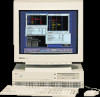
as a standalone product. Figure 8-1 depicts the monitor. Table 8-1 lists pertinent information. Figure 8-1. HP A2088A Monitor Table 8-1. HP A2088A Specifications Product Number HP A2088A Exchange Part Number A2088-69001 Size 19 inch (1280x1024 pixels) Refresh Rate 72 Hz 8-2 Service Notes - HP Model 715/100 | hp 9000 series 700 model 715 workstations service handbook (a - Page 144
Pixel period Horizontal display Vertical display 135.00 MHz pulse width Horizontal back porch Horizontal blanking Horizontal display time 78.125 kHz 12.800 ms front porch Vertical sync pulse width Vertical back porch Vertical blanking Vertical display time 1 72.005 Hz 13.888 ms (1 V) (1085 lines - HP Model 715/100 | hp 9000 series 700 model 715 workstations service handbook (a - Page 145
information. Figure 8-2. HP A2094 Monitor Table 8-2. HP A2094 Specifications Product Number HP A2094A Exchange Part Number A2094-69001 Hemisphere Northern HP A2094B 2090-0315 Southern Size 19 inch (1280x1024 pixels) 19 inch (1280x1024 pixels) Refresh Rate 72 Hz 72 Hz 8-4 Service Notes - HP Model 715/100 | hp 9000 series 700 model 715 workstations service handbook (a - Page 146
Pixel period Horizontal display Vertical display 135.00 MHz pulse width Horizontal back porch Horizontal blanking Horizontal display time 78.125 kHz 12.800 ms front porch Vertical sync pulse width Vertical back porch Vertical blanking Vertical display time 1 72.005 Hz 13.888 ms (1 V) (1085 lines - HP Model 715/100 | hp 9000 series 700 model 715 workstations service handbook (a - Page 147
Boot Failure, 4-13-4-14 Boot ROM Diagnostics, 4-1 C Cable Connections 715/64, 715/80, and 715/100, 5-13-5-16 CD-ROM audio, 5-15 SCSI, 5-14-5-16 Calendar , 1-11-1-12 HP-HIL, 1-9 network, 1-10 options, 1-11-1-12 parallel, 1-9 RS-232, 1-9-1-10 SCSI, 1-9 serial, 1-9-1-10 Controls monitor, 1-13 system - HP Model 715/100 | hp 9000 series 700 model 715 workstations service handbook (a - Page 148
715/50, 5-47 715/64, 5-48 715/75, 5-49 715/80, 5-48 715/C, 5-47 CRX Graphics assembly removal, 5-35-5-38 configuring, 3-18 dual monitor system, 3-21-3-23 single monitor system, 3-18-3-20 external processor removal, 5-6 troubleshooting manual, 7-1 reference manuals, 7-1 service manuals 5-42-5-44 power - HP Model 715/100 | hp 9000 series 700 model 715 workstations service handbook (a - Page 149
troubleshooting, 4-30-4-31 I Indicators LED, system unit, 1-5-1-6 monitor, 1-13 ISL Diagnostics, 4-17-4-20 ISL Environment, 4-17-4-20 altpath command, 4-19 conspath command, 4-19 display command, 4-19 listautofl command, 4-19 lsautofl command, 4-19 primpath command, 4-19 readss command, 4-19 support - HP Model 715/100 | hp 9000 series 700 model 715 workstations service handbook (a - Page 150
GB low profile drive, 3-11 HP Winchester drives, 3-5, 3-10 Control (TOC), 1-4 System Block Diagram, 6-3 System Unit controls, 1-4-1-5 installation information, 2-2 LEDs, 1-5-1-6 preventive maintenance, 2-2 System Verification Tests, SupportWave, 4-21-4-29 T Terminators, 3-1 Troubleshooting
-
 1
1 -
 2
2 -
 3
3 -
 4
4 -
 5
5 -
 6
6 -
 7
7 -
8
-
9
-
10
-
11
-
12
-
13
-
14
-
15
-
16
-
17
-
18
-
19
-
20
-
21
-
22
-
23
-
24
-
25
-
26
-
27
-
28
-
29
-
30
-
31
-
32
-
33
-
34
-
35
-
36
-
37
-
38
-
39
-
40
-
41
-
42
-
43
-
44
-
45
-
46
-
47
-
48
-
49
-
50
-
51
-
52
-
53
-
54
-
55
-
56
-
57
-
58
-
59
-
60
-
61
-
62
-
63
-
64
-
65
-
66
-
67
-
68
-
69
-
70
-
71
-
72
-
73
-
74
-
75
-
76
-
77
-
78
-
79
-
80
-
81
-
82
-
83
-
84
-
85
-
86
-
87
-
88
-
89
-
90
-
91
-
92
-
93
-
94
-
95
-
96
-
97
-
98
-
99
-
100
-
101
-
102
-
103
-
104
-
105
-
106
-
107
-
108
-
109
-
110
-
111
-
112
-
113
-
114
-
115
-
116
-
117
-
118
-
119
-
120
-
121
-
122
-
123
-
124
-
125
-
126
-
127
-
128
-
129
-
130
-
131
-
132
-
133
-
134
-
135
-
136
-
137
-
138
-
139
-
140
-
141
-
142
-
143
-
144
-
145
-
146
-
147
-
148
-
149
-
150
 |
 |

Service Handbook
HP 9000 Series 700
Model 715 Workstations
HP Part Number. A2600–90039
Click to go to the Table of Contents
3404 East Harmony Road, Fort Collins, CO. 80525