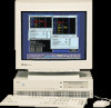
HP Model 715/100 hp 9000 series 700 model 715 workstations service handbook (a - Page 23
Network Connector, Built-In Graphics Connector
 |
View all HP Model 715/100 manuals
Add to My Manuals
Save this manual to your list of manuals |
Page 23 highlights
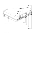
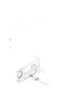
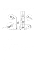
Table 1-2. Serial I/O Pins Pin No. 1 2 3 4 5 6 7 8 9 Signal DCD RXD TXD DTR GND DSR RTS CTS RI Description Data Carrier Detect Receive Data Transmit Data Data Terminal Ready Ground Data Set Ready Request To Send Clear To Send Ring Indicator 802.3 Network Connector Figure 1-3 shows the location of the connector for the 802.3 (ETHERNET) network. Connect an ETHERNET transceiver to this connector for communicating with a network. Built-In Graphics Connector If the workstation does not have the CRX, HCRX, or VISUALIZE graphics option installed, use the built-in graphics connector to connect the monitor's video cable to the system. If the workstation is equipped with optional graphics, connect the monitor or external graphics unit to the optional graphics connect as described below. If you are setting up a dual monitor system, connect one monitor to the built-in graphics connector and the other monitor to the optional graphics connector. 1-10 Product Information
-
 1
1 -
2
-
3
-
4
-
5
-
6
-
7
-
8
-
9
-
10
-
11
-
12
-
13
-
14
-
15
-
16
-
17
-
 18
18 -
 19
19 -
 20
20 -
 21
21 -
 22
22 -
 23
23 -
 24
24 -
 25
25 -
 26
26 -
 27
27 -
 28
28 -
29
-
30
-
31
-
32
-
33
-
34
-
35
-
36
-
37
-
38
-
39
-
40
-
41
-
42
-
43
-
44
-
45
-
46
-
47
-
48
-
49
-
50
-
51
-
52
-
53
-
54
-
55
-
56
-
57
-
58
-
59
-
60
-
61
-
62
-
63
-
64
-
65
-
66
-
67
-
68
-
69
-
70
-
71
-
72
-
73
-
74
-
75
-
76
-
77
-
78
-
79
-
80
-
81
-
82
-
83
-
84
-
85
-
86
-
87
-
88
-
89
-
90
-
91
-
92
-
93
-
94
-
95
-
96
-
97
-
98
-
99
-
100
-
101
-
102
-
103
-
104
-
105
-
106
-
107
-
108
-
109
-
110
-
111
-
112
-
113
-
114
-
115
-
116
-
117
-
118
-
119
-
120
-
121
-
122
-
123
-
124
-
125
-
126
-
127
-
128
-
129
-
130
-
131
-
132
-
133
-
134
-
135
-
136
-
137
-
138
-
139
-
140
-
141
-
142
-
143
-
144
-
145
-
146
-
147
-
148
-
149
-
150
 |
 |
