HP Model 715/100 hp 9000 series 700 model 715 workstations service handbook (a - Page 120
CRX and HCRX Graphics
 |
View all HP Model 715/100 manuals
Add to My Manuals
Save this manual to your list of manuals |
Page 120 highlights
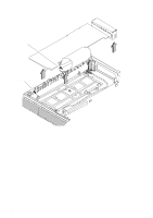
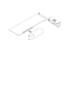
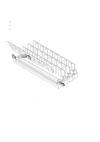
CRX and HCRX Graphics Before removing the CRX or HCRX graphics board, perform the following steps: S Remove the optional external graphics processor (if installed). S Remove the floor stand. S Open the system unit. Push the retaining clips away from the CRX or HCRX graphics board to release the board. Disconnect the flex cable connector from the CPU board and pull the board and connector bucket straight up to remove the board, as shown in Figure 5-36. NOTICES: When disconnecting the flex cable connector from the CPU connector, pull straight up on both ends of the connector at the same time. When connecting the flex cable to the CPU board connector carefully align the flex cable connector and the connector on the CPU board. Make sure that you press down evenly and firmly on both sides of the connector to ensure that it seats evenly and completely. Following these guidelines ensures you of a good mechanical and electrical connection and that you do not bend any of the pins on the CPU connector. When installing the graphics processor to system cable for the CRX-48Z graphics, you should use a small flatblade screwdriver to firmly tighten the thumbscrews on the cable connectors. Field Replaceable Units 5-35
-
 1
1 -
2
-
3
-
4
-
5
-
6
-
7
-
8
-
9
-
10
-
11
-
12
-
13
-
14
-
15
-
16
-
17
-
18
-
19
-
20
-
21
-
22
-
23
-
24
-
25
-
26
-
27
-
28
-
29
-
30
-
31
-
32
-
33
-
34
-
35
-
36
-
37
-
38
-
39
-
40
-
41
-
42
-
43
-
44
-
45
-
46
-
47
-
48
-
49
-
50
-
51
-
52
-
53
-
54
-
55
-
56
-
57
-
58
-
59
-
60
-
61
-
62
-
63
-
64
-
65
-
66
-
67
-
68
-
69
-
70
-
71
-
72
-
73
-
74
-
75
-
76
-
77
-
78
-
79
-
80
-
81
-
82
-
83
-
84
-
85
-
86
-
87
-
88
-
89
-
90
-
91
-
92
-
93
-
94
-
95
-
96
-
97
-
98
-
99
-
100
-
101
-
102
-
103
-
104
-
105
-
106
-
107
-
108
-
109
-
110
-
111
-
112
-
113
-
114
-
 115
115 -
 116
116 -
 117
117 -
 118
118 -
 119
119 -
 120
120 -
 121
121 -
 122
122 -
 123
123 -
 124
124 -
 125
125 -
126
-
127
-
128
-
129
-
130
-
131
-
132
-
133
-
134
-
135
-
136
-
137
-
138
-
139
-
140
-
141
-
142
-
143
-
144
-
145
-
146
-
147
-
148
-
149
-
150
 |
 |
