HP Model 715/100 hp 9000 series 700 model 715 workstations service handbook (a - Page 118
Slide Bucket into, Channels of, Connector Slot, Align Standoffs and, Holes on Adapter, Board and CPU
 |
View all HP Model 715/100 manuals
Add to My Manuals
Save this manual to your list of manuals |
Page 118 highlights
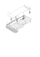
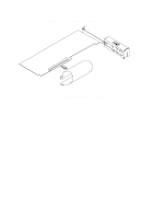
Slide the connector bucket partway into the channels of the connector slot on the rear of the system unit, as shown in Figure 5-34. Align the connector on the adapter board with the connector on the processor board, and carefully press the two connectors together. Ensure that the standoffs are aligned with the standoffs in the CPU board. Press on both the connector bucket and the adapter board to secure the assembly to the system unit. Slide Bucket into Channels of Connector Slot Align Standoffs and Holes on Adapter Board and CPU Board Insert Connector on Adapter Board Here Figure 5-34. Inserting the EISA Assembly into the System Unit (Retaining Clips) Field Replaceable Units 5-33
-
 1
1 -
2
-
3
-
4
-
5
-
6
-
7
-
8
-
9
-
10
-
11
-
12
-
13
-
14
-
15
-
16
-
17
-
18
-
19
-
20
-
21
-
22
-
23
-
24
-
25
-
26
-
27
-
28
-
29
-
30
-
31
-
32
-
33
-
34
-
35
-
36
-
37
-
38
-
39
-
40
-
41
-
42
-
43
-
44
-
45
-
46
-
47
-
48
-
49
-
50
-
51
-
52
-
53
-
54
-
55
-
56
-
57
-
58
-
59
-
60
-
61
-
62
-
63
-
64
-
65
-
66
-
67
-
68
-
69
-
70
-
71
-
72
-
73
-
74
-
75
-
76
-
77
-
78
-
79
-
80
-
81
-
82
-
83
-
84
-
85
-
86
-
87
-
88
-
89
-
90
-
91
-
92
-
93
-
94
-
95
-
96
-
97
-
98
-
99
-
100
-
101
-
102
-
103
-
104
-
105
-
106
-
107
-
108
-
109
-
110
-
111
-
112
-
 113
113 -
 114
114 -
 115
115 -
 116
116 -
 117
117 -
 118
118 -
 119
119 -
 120
120 -
 121
121 -
 122
122 -
 123
123 -
124
-
125
-
126
-
127
-
128
-
129
-
130
-
131
-
132
-
133
-
134
-
135
-
136
-
137
-
138
-
139
-
140
-
141
-
142
-
143
-
144
-
145
-
146
-
147
-
148
-
149
-
150
 |
 |

5–33
Field Replaceable Units
Slide the connector bucket
partway
into the channels of the connector slot on the rear
of the system unit, as shown in Figure 5–34.
Align the connector on the adapter board with the connector on the processor board,
and carefully press the two connectors together. Ensure that the standoffs are aligned
with the standoffs in the CPU board. Press on both the connector bucket and the
adapter board to secure the assembly to the system unit.
Slide Bucket into
Channels of
Connector Slot
Align Standoffs and
Holes on Adapter
Board and CPU Board
Insert Connector on
Adapter Board Here
Figure 5–34.
Inserting the EISA Assembly into the System Unit (Retaining Clips)