HP Model 715/100 hp 9000 series 700 model 715 workstations service handbook (a - Page 131
Removing the Processor Board
 |
View all HP Model 715/100 manuals
Add to My Manuals
Save this manual to your list of manuals |
Page 131 highlights
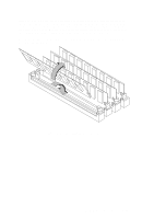
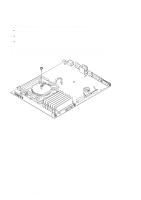
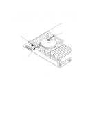
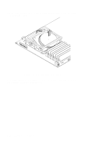
NOTICE: Tolerances between the processor board and the chassis are very close. You must use care when removing and replacing the processor board to avoid causing damage to the board. To install the processor board, use a wide, flat object to lever the board toward the rear Figure 5-45. Removing the Processor Board 5-46 Field Replaceable Units
-
 1
1 -
2
-
3
-
4
-
5
-
6
-
7
-
8
-
9
-
10
-
11
-
12
-
13
-
14
-
15
-
16
-
17
-
18
-
19
-
20
-
21
-
22
-
23
-
24
-
25
-
26
-
27
-
28
-
29
-
30
-
31
-
32
-
33
-
34
-
35
-
36
-
37
-
38
-
39
-
40
-
41
-
42
-
43
-
44
-
45
-
46
-
47
-
48
-
49
-
50
-
51
-
52
-
53
-
54
-
55
-
56
-
57
-
58
-
59
-
60
-
61
-
62
-
63
-
64
-
65
-
66
-
67
-
68
-
69
-
70
-
71
-
72
-
73
-
74
-
75
-
76
-
77
-
78
-
79
-
80
-
81
-
82
-
83
-
84
-
85
-
86
-
87
-
88
-
89
-
90
-
91
-
92
-
93
-
94
-
95
-
96
-
97
-
98
-
99
-
100
-
101
-
102
-
103
-
104
-
105
-
106
-
107
-
108
-
109
-
110
-
111
-
112
-
113
-
114
-
115
-
116
-
117
-
118
-
119
-
120
-
121
-
122
-
123
-
124
-
125
-
 126
126 -
 127
127 -
 128
128 -
 129
129 -
 130
130 -
 131
131 -
 132
132 -
 133
133 -
 134
134 -
 135
135 -
 136
136 -
137
-
138
-
139
-
140
-
141
-
142
-
143
-
144
-
145
-
146
-
147
-
148
-
149
-
150
 |
 |

5–46
Field Replaceable Units
NOTICE:
Tolerances between the processor board and the chas-
sis are very close. You must use care when removing
and replacing the processor board to avoid causing
damage to the board.
To install the processor
board, use a wide, flat
object to lever the
board toward
the rear
Figure 5–45.
Removing the Processor Board