HP Model 715/100 hp 9000 series 700 model 715 workstations service handbook (a - Page 47
Memory Connector Configuration
 |
View all HP Model 715/100 manuals
Add to My Manuals
Save this manual to your list of manuals |
Page 47 highlights
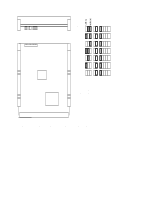
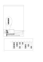
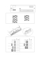
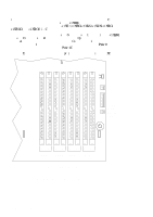
r c15E1GG1 c15E1GG i.C sG A sR 1 E C r c15ERR -c15Ei1 c15E5G1 c15EaS1 c15Ec51 c15EhG1 sG s Cp Co Pair 1C prr 2 r c15ERR1 1 Pair 0 i 5C Right Side of System Unit A B Pair 3 A B Pair 2 A B Pair 1 A B Pair 0 Front of System Unit Figure 3-15. Memory Connector Configuration 3-16 Configuration
-
 1
1 -
2
-
3
-
4
-
5
-
6
-
7
-
8
-
9
-
10
-
11
-
12
-
13
-
14
-
15
-
16
-
17
-
18
-
19
-
20
-
21
-
22
-
23
-
24
-
25
-
26
-
27
-
28
-
29
-
30
-
31
-
32
-
33
-
34
-
35
-
36
-
37
-
38
-
39
-
40
-
41
-
 42
42 -
 43
43 -
 44
44 -
 45
45 -
 46
46 -
 47
47 -
 48
48 -
 49
49 -
 50
50 -
 51
51 -
 52
52 -
53
-
54
-
55
-
56
-
57
-
58
-
59
-
60
-
61
-
62
-
63
-
64
-
65
-
66
-
67
-
68
-
69
-
70
-
71
-
72
-
73
-
74
-
75
-
76
-
77
-
78
-
79
-
80
-
81
-
82
-
83
-
84
-
85
-
86
-
87
-
88
-
89
-
90
-
91
-
92
-
93
-
94
-
95
-
96
-
97
-
98
-
99
-
100
-
101
-
102
-
103
-
104
-
105
-
106
-
107
-
108
-
109
-
110
-
111
-
112
-
113
-
114
-
115
-
116
-
117
-
118
-
119
-
120
-
121
-
122
-
123
-
124
-
125
-
126
-
127
-
128
-
129
-
130
-
131
-
132
-
133
-
134
-
135
-
136
-
137
-
138
-
139
-
140
-
141
-
142
-
143
-
144
-
145
-
146
-
147
-
148
-
149
-
150
 |
 |

3–16
Configuration
r %’)0
’ ) * %,*+
#&*+ $$
#& ( #)* ’
+"
* %
% %’)0
(
#+0C
’,
% 0
#&*+ $$
,(
+’
+")
( #)*
’) +"
r’
$
c15ERR
&
,( +’
’,)
( #)*
’
% %’)0
’ ) *
’)
$$
’+" ) %’
$* -c15Ei1
c15E5G1
c15EaS1
c15Ec51
c15EhG1
c15E1GG1
&
c15E1GG i.C
"
% %’)0
’&&
+’)*
)
$
$
s #) G
+")’,!" s #) 2
’)
+"
r’
$
c15ERR1
&
s #)
G
+")’,!"
s #)
R
’)
$$
+"
’+" ) %’
$*C
p&*+ $$
% %’)0
’ ) *
#& +"
$’. *+A&,%
)
%(+0
’&&
+’) ( #)
#)*+C
o’)
/ %($ 1
#
0’, " -
+.’
( #)*
’
% %’)0
’ ) *1
#&*+ $$
+"
#)*+ ( #) #& +"
’&&
+’)* $
$
Pair
0
&
+"
*
’&
( #)
#&
+"
’&&
+’)* $
$
Pair 1
C
%’- $E) ($
% &+
()’
,) *
’)
prr*
)
()’-#
#& i" (+ )
5C
Pair 0
Pair 1
Pair 2
Pair 3
A
B
Front of System Unit
Right
Side of
System
Unit
A
B
A
B
A
B
Figure 3–15.
Memory Connector Configuration