HP Pro 3500 Maintenance & Service Guide HP Pro 3400, 3405 and 3410 Microto - Page 106
Removing Drives, Removing an Optical Drive
 |
View all HP Pro 3500 manuals
Add to My Manuals
Save this manual to your list of manuals |
Page 106 highlights
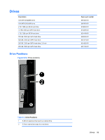
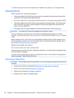
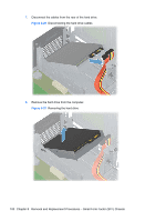
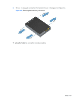
To verify the type and size of the storage devices installed in the computer, run Computer Setup. Removing Drives When installing drives, follow these guidelines: ● The primary Serial ATA (SATA) hard drive must be connected to the dark blue primary SATA connector on the system board labeled SATA0. ● Connect an optical drive to the light blue SATA connector on the system board labeled SATA2. ● The power cables for the SATA drives connect directly to the power supply. The primary hard drive connects to the power connector labeled P4. the primary optical drive connects to the power connector labeled P3. ● The system does not support Parallel ATA (PATA) optical drives or PATA hard drives. CAUTION: To prevent loss of work and damage to the computer or drive: If you are inserting or removing a drive, shut down the operating system properly, turn off the computer, and unplug the power cord. Do not remove a drive while the computer is on or in standby mode. Before handling a drive, ensure that you are discharged of static electricity. While handling a drive, avoid touching the connector. For more information about preventing electrostatic damage, refer to Electrostatic Discharge Information on page 36. Handle a drive carefully; do not drop it. Do not use excessive force when inserting a drive. Avoid exposing a hard drive to liquids, temperature extremes, or products that have magnetic fields such as monitors or speakers. If a drive must be mailed, place the drive in a bubble-pack mailer or other protective packaging and label the package "Fragile: Handle With Care." Removing an Optical Drive CAUTION: All removable media should be taken out of a drive before removing the drive from the computer. 1. Prepare the computer for disassembly (Preparation for Disassembly on page 80). 2. Remove the access panel (Access Panel on page 81). 3. Remove the front bezel (Front Bezel on page 83). 4. Rotate the drive cage to its upright position. 96 Chapter 8 Removal and Replacement Procedures - Small Form Factor (SFF) Chassis
-
 1
1 -
2
-
3
-
4
-
5
-
6
-
7
-
8
-
9
-
10
-
11
-
12
-
13
-
14
-
15
-
16
-
17
-
18
-
19
-
20
-
21
-
22
-
23
-
24
-
25
-
26
-
27
-
28
-
29
-
30
-
31
-
32
-
33
-
34
-
35
-
36
-
37
-
38
-
39
-
40
-
41
-
42
-
43
-
44
-
45
-
46
-
47
-
48
-
49
-
50
-
51
-
52
-
53
-
54
-
55
-
56
-
57
-
58
-
59
-
60
-
61
-
62
-
63
-
64
-
65
-
66
-
67
-
68
-
69
-
70
-
71
-
72
-
73
-
74
-
75
-
76
-
77
-
78
-
79
-
80
-
81
-
82
-
83
-
84
-
85
-
86
-
87
-
88
-
89
-
90
-
91
-
92
-
93
-
94
-
95
-
96
-
97
-
98
-
99
-
100
-
 101
101 -
 102
102 -
 103
103 -
 104
104 -
 105
105 -
 106
106 -
 107
107 -
 108
108 -
 109
109 -
 110
110 -
 111
111 -
112
-
113
-
114
-
115
-
116
-
117
-
118
-
119
-
120
-
121
-
122
-
123
-
124
-
125
-
126
-
127
-
128
-
129
-
130
-
131
-
132
-
133
-
134
-
135
-
136
-
137
-
138
-
139
-
140
-
141
-
142
-
143
-
144
-
145
-
146
-
147
-
148
-
149
-
150
-
151
-
152
-
153
-
154
-
155
-
156
-
157
-
158
-
159
-
160
-
161
-
162
-
163
-
164
-
165
-
166
-
167
-
168
-
169
-
170
-
171
-
172
-
173
-
174
-
175
-
176
-
177
-
178
-
179
-
180
-
181
-
182
-
183
-
184
-
185
-
186
-
187
-
188
-
189
-
190
-
191
-
192
-
193
-
194
-
195
-
196
-
197
-
198
-
199
-
200
-
201
 |
 |