HP Pro 3500 Maintenance & Service Guide HP Pro 3400, 3405 and 3410 Microto - Page 117
Fan Assembly
 |
View all HP Pro 3500 manuals
Add to My Manuals
Save this manual to your list of manuals |
Page 117 highlights
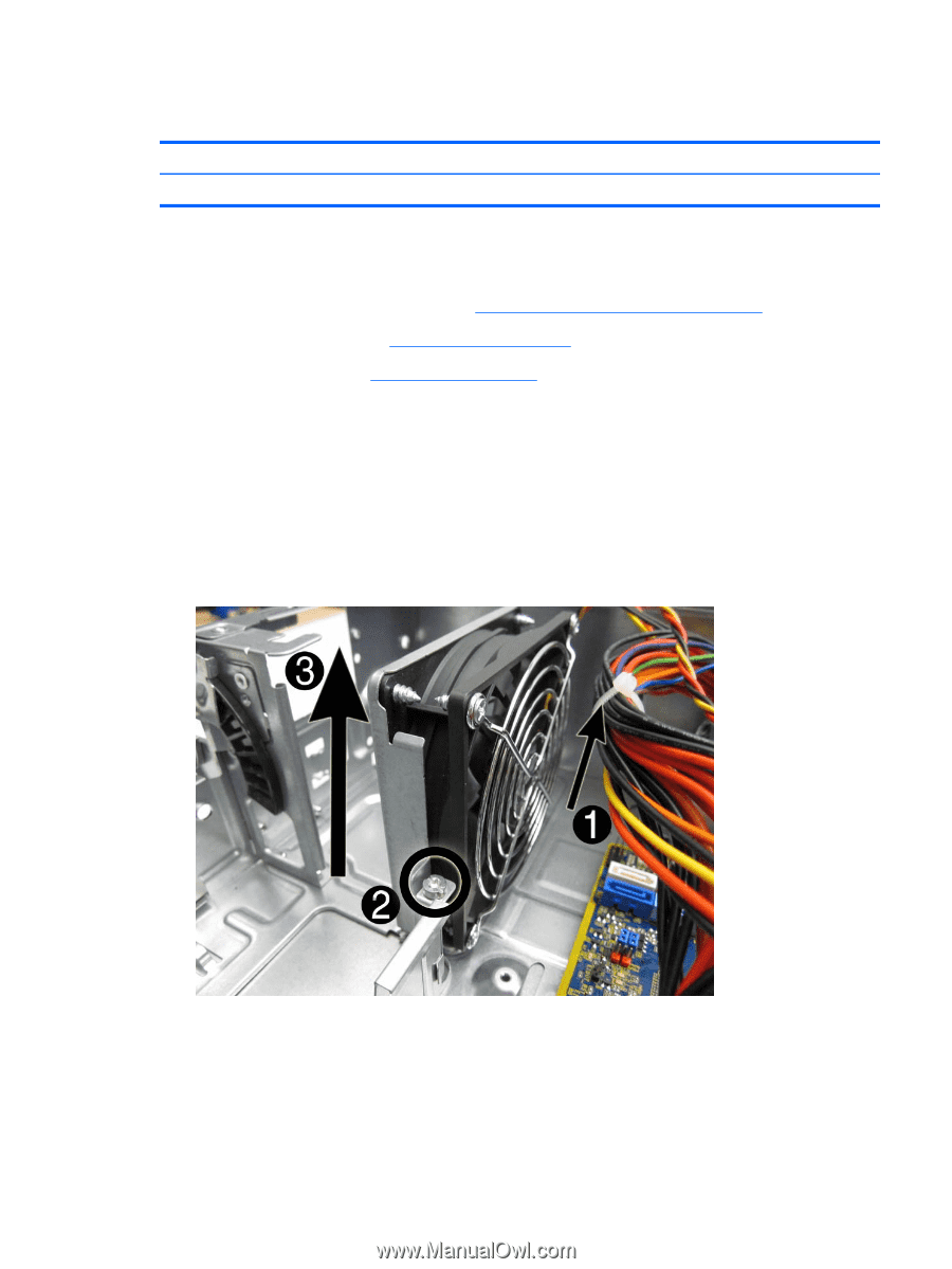
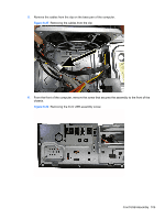
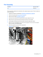
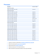
Fan Assembly Description Fan Spare part number 656834-001 The fan assembly is attached to the inside floor of the chassis using two screws. The fan is inside of a removal metal cage. 1. Prepare the computer for disassembly (Preparation for Disassembly on page 80). 2. Remove the access panel (Access Panel on page 81). 3. Remove the front bezel (Front Bezel on page 83). 4. Disconnect the fan cable from the system board connector labeled SYS_FAN. 5. Remove the Torx screw that secures the left side of the fan to the computer. 6. Cut the plastic tie (1) that secures the fan cable to the power supply power cables. 7. Remove the two screws (2) that secure the fan to the computer. The screw near the computer side is not shown in the following image. 8. Lift the fan assembly up and out of the computer (3). Figure 8-30 Removing the fan Fan Assembly 107
-
 1
1 -
2
-
3
-
4
-
5
-
6
-
7
-
8
-
9
-
10
-
11
-
12
-
13
-
14
-
15
-
16
-
17
-
18
-
19
-
20
-
21
-
22
-
23
-
24
-
25
-
26
-
27
-
28
-
29
-
30
-
31
-
32
-
33
-
34
-
35
-
36
-
37
-
38
-
39
-
40
-
41
-
42
-
43
-
44
-
45
-
46
-
47
-
48
-
49
-
50
-
51
-
52
-
53
-
54
-
55
-
56
-
57
-
58
-
59
-
60
-
61
-
62
-
63
-
64
-
65
-
66
-
67
-
68
-
69
-
70
-
71
-
72
-
73
-
74
-
75
-
76
-
77
-
78
-
79
-
80
-
81
-
82
-
83
-
84
-
85
-
86
-
87
-
88
-
89
-
90
-
91
-
92
-
93
-
94
-
95
-
96
-
97
-
98
-
99
-
100
-
101
-
102
-
103
-
104
-
105
-
106
-
107
-
108
-
109
-
110
-
111
-
 112
112 -
 113
113 -
 114
114 -
 115
115 -
 116
116 -
 117
117 -
 118
118 -
 119
119 -
 120
120 -
 121
121 -
 122
122 -
123
-
124
-
125
-
126
-
127
-
128
-
129
-
130
-
131
-
132
-
133
-
134
-
135
-
136
-
137
-
138
-
139
-
140
-
141
-
142
-
143
-
144
-
145
-
146
-
147
-
148
-
149
-
150
-
151
-
152
-
153
-
154
-
155
-
156
-
157
-
158
-
159
-
160
-
161
-
162
-
163
-
164
-
165
-
166
-
167
-
168
-
169
-
170
-
171
-
172
-
173
-
174
-
175
-
176
-
177
-
178
-
179
-
180
-
181
-
182
-
183
-
184
-
185
-
186
-
187
-
188
-
189
-
190
-
191
-
192
-
193
-
194
-
195
-
196
-
197
-
198
-
199
-
200
-
201
 |
 |