HP Pro 3500 Maintenance & Service Guide HP Pro 3400, 3405 and 3410 Microto - Page 120
Caution
 |
View all HP Pro 3500 manuals
Add to My Manuals
Save this manual to your list of manuals |
Page 120 highlights
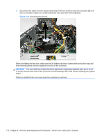
4. Disconnect the cable from the system board (1), lift the fan sink from atop the processor (2) and set it on its side to keep from contaminating the work area with thermal grease. Figure 8-33 Removing the fan sink When reinstalling the fan sink, make sure that its bottom has been cleaned with an alcohol wipe and fresh thermal grease has been applied to the top of the processor. CAUTION: Fan sink retaining screws should be tightened in diagonally opposite pairs (as in an X) to evenly seat the heat sink on the processor to avoid damage that could require replacing the system board. Failure to install the fan duct may cause the computer to overheat. 110 Chapter 8 Removal and Replacement Procedures - Small Form Factor (SFF) Chassis
-
 1
1 -
2
-
3
-
4
-
5
-
6
-
7
-
8
-
9
-
10
-
11
-
12
-
13
-
14
-
15
-
16
-
17
-
18
-
19
-
20
-
21
-
22
-
23
-
24
-
25
-
26
-
27
-
28
-
29
-
30
-
31
-
32
-
33
-
34
-
35
-
36
-
37
-
38
-
39
-
40
-
41
-
42
-
43
-
44
-
45
-
46
-
47
-
48
-
49
-
50
-
51
-
52
-
53
-
54
-
55
-
56
-
57
-
58
-
59
-
60
-
61
-
62
-
63
-
64
-
65
-
66
-
67
-
68
-
69
-
70
-
71
-
72
-
73
-
74
-
75
-
76
-
77
-
78
-
79
-
80
-
81
-
82
-
83
-
84
-
85
-
86
-
87
-
88
-
89
-
90
-
91
-
92
-
93
-
94
-
95
-
96
-
97
-
98
-
99
-
100
-
101
-
102
-
103
-
104
-
105
-
106
-
107
-
108
-
109
-
110
-
111
-
112
-
113
-
114
-
 115
115 -
 116
116 -
 117
117 -
 118
118 -
 119
119 -
 120
120 -
 121
121 -
 122
122 -
 123
123 -
 124
124 -
 125
125 -
126
-
127
-
128
-
129
-
130
-
131
-
132
-
133
-
134
-
135
-
136
-
137
-
138
-
139
-
140
-
141
-
142
-
143
-
144
-
145
-
146
-
147
-
148
-
149
-
150
-
151
-
152
-
153
-
154
-
155
-
156
-
157
-
158
-
159
-
160
-
161
-
162
-
163
-
164
-
165
-
166
-
167
-
168
-
169
-
170
-
171
-
172
-
173
-
174
-
175
-
176
-
177
-
178
-
179
-
180
-
181
-
182
-
183
-
184
-
185
-
186
-
187
-
188
-
189
-
190
-
191
-
192
-
193
-
194
-
195
-
196
-
197
-
198
-
199
-
200
-
201
 |
 |

4.
Disconnect the cable from the system board
(1)
, lift the fan sink from atop the processor
(2)
and
set it on its side to keep from contaminating the work area with thermal grease.
Figure 8-33
Removing the fan sink
When reinstalling the fan sink, make sure that its bottom has been cleaned with an alcohol wipe and
fresh thermal grease has been applied to the top of the processor.
CAUTION:
Fan sink retaining screws should be tightened in diagonally opposite pairs (as in an X)
to evenly seat the heat sink on the processor to avoid damage that could require replacing the system
board.
Failure to install the fan duct may cause the computer to overheat.
110
Chapter 8
Removal and Replacement Procedures – Small Form Factor (SFF) Chassis