HP Pro 3500 Maintenance & Service Guide HP Pro 3400, 3405 and 3410 Microto - Page 81
Fan Sink Assembly
 |
View all HP Pro 3500 manuals
Add to My Manuals
Save this manual to your list of manuals |
Page 81 highlights
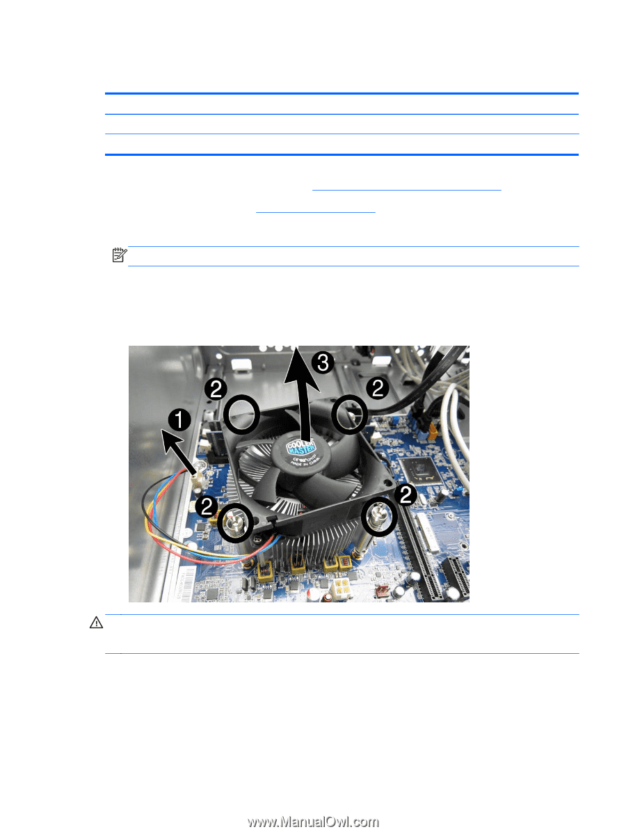
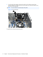
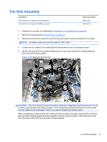
Fan Sink Assembly Description Fan sink for use in models with Intel processors Fan sink for use in models with AMD processors Spare part number 667727-001 657402-001 1. Prepare the computer for disassembly (Preparation for Disassembly on page 43). 2. Remove the access panel (Access Panel on page 44). 3. Disconnect the fan sink cable from the white system board connector labeled CPU FAN (1). NOTE: On AMD models the connector label is CPU_FAN1. 4. Loosen the four captive Torx screws (2) that secure the fan sink to the system board. 5. Lift the heat sink from the processor (3) and set it on its side to keep from contaminating the work area with thermal grease. Figure 7-25 Removing the fan sink CAUTION: Heat sink retaining screws should be tightened in diagonally opposite pairs (as in an X) to evenly seat the heat sink to the processor. This is especially important as the pins on the socket are very fragile and any damage to them may require replacing the system board. When reinstalling an existing heat sink, make sure that its bottom has been cleaned with an alcohol wipe and fresh thermal grease has been applied to the top of the processor. New heat sinks come from the factory with fresh thermal grease already applied. Fan Sink Assembly 71
-
 1
1 -
2
-
3
-
4
-
5
-
6
-
7
-
8
-
9
-
10
-
11
-
12
-
13
-
14
-
15
-
16
-
17
-
18
-
19
-
20
-
21
-
22
-
23
-
24
-
25
-
26
-
27
-
28
-
29
-
30
-
31
-
32
-
33
-
34
-
35
-
36
-
37
-
38
-
39
-
40
-
41
-
42
-
43
-
44
-
45
-
46
-
47
-
48
-
49
-
50
-
51
-
52
-
53
-
54
-
55
-
56
-
57
-
58
-
59
-
60
-
61
-
62
-
63
-
64
-
65
-
66
-
67
-
68
-
69
-
70
-
71
-
72
-
73
-
74
-
75
-
 76
76 -
 77
77 -
 78
78 -
 79
79 -
 80
80 -
 81
81 -
 82
82 -
 83
83 -
 84
84 -
 85
85 -
 86
86 -
87
-
88
-
89
-
90
-
91
-
92
-
93
-
94
-
95
-
96
-
97
-
98
-
99
-
100
-
101
-
102
-
103
-
104
-
105
-
106
-
107
-
108
-
109
-
110
-
111
-
112
-
113
-
114
-
115
-
116
-
117
-
118
-
119
-
120
-
121
-
122
-
123
-
124
-
125
-
126
-
127
-
128
-
129
-
130
-
131
-
132
-
133
-
134
-
135
-
136
-
137
-
138
-
139
-
140
-
141
-
142
-
143
-
144
-
145
-
146
-
147
-
148
-
149
-
150
-
151
-
152
-
153
-
154
-
155
-
156
-
157
-
158
-
159
-
160
-
161
-
162
-
163
-
164
-
165
-
166
-
167
-
168
-
169
-
170
-
171
-
172
-
173
-
174
-
175
-
176
-
177
-
178
-
179
-
180
-
181
-
182
-
183
-
184
-
185
-
186
-
187
-
188
-
189
-
190
-
191
-
192
-
193
-
194
-
195
-
196
-
197
-
198
-
199
-
200
-
201
 |
 |