HP Pro 3500 Maintenance & Service Guide HP Pro 3400, 3405 and 3410 Microto - Page 122
CAUTION, the spares kit.
 |
View all HP Pro 3500 manuals
Add to My Manuals
Save this manual to your list of manuals |
Page 122 highlights
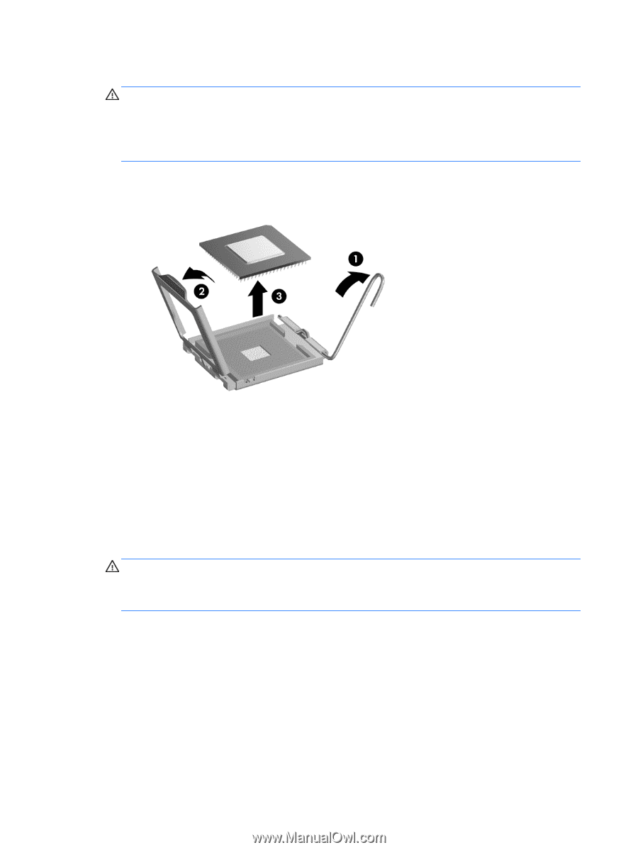
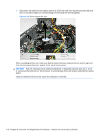
6. Carefully lift the processor from the socket (3). CAUTION: Do NOT handle the pins in the processor socket. These pins are very fragile and handling them could cause irreparable damage. Once pins are damaged it may be necessary to replace the system board. The heat sink must be installed within 24 hours of installing the processor to prevent damage to the processor's solder connections. Figure 8-34 Removing the processor To install a new processor: 1. Place the processor in its socket and close the retainer. Make sure the slot in the processor fits into the post on the socket. 2. Secure the locking lever. If reusing the existing heat sink, go to step 3. If using a new heat sink, go to step 6. 3. If reusing the existing fan sink, clean the bottom of the fan sink with the alcohol pad provided in the spares kit. CAUTION: Before reinstalling the fan sink you must clean the top of the processor and the bottom of the fan sink with an alcohol pad supplied in the spares kit. After the alcohol has evaporated, apply thermal grease to the top of the processor from the syringe supplied in the spares kit. 4. Apply the thermal grease provided in the spares kit to the top of the processor and install the fan sink atop the processor. 5. Go to step 7. 112 Chapter 8 Removal and Replacement Procedures - Small Form Factor (SFF) Chassis
-
 1
1 -
2
-
3
-
4
-
5
-
6
-
7
-
8
-
9
-
10
-
11
-
12
-
13
-
14
-
15
-
16
-
17
-
18
-
19
-
20
-
21
-
22
-
23
-
24
-
25
-
26
-
27
-
28
-
29
-
30
-
31
-
32
-
33
-
34
-
35
-
36
-
37
-
38
-
39
-
40
-
41
-
42
-
43
-
44
-
45
-
46
-
47
-
48
-
49
-
50
-
51
-
52
-
53
-
54
-
55
-
56
-
57
-
58
-
59
-
60
-
61
-
62
-
63
-
64
-
65
-
66
-
67
-
68
-
69
-
70
-
71
-
72
-
73
-
74
-
75
-
76
-
77
-
78
-
79
-
80
-
81
-
82
-
83
-
84
-
85
-
86
-
87
-
88
-
89
-
90
-
91
-
92
-
93
-
94
-
95
-
96
-
97
-
98
-
99
-
100
-
101
-
102
-
103
-
104
-
105
-
106
-
107
-
108
-
109
-
110
-
111
-
112
-
113
-
114
-
115
-
116
-
 117
117 -
 118
118 -
 119
119 -
 120
120 -
 121
121 -
 122
122 -
 123
123 -
 124
124 -
 125
125 -
 126
126 -
 127
127 -
128
-
129
-
130
-
131
-
132
-
133
-
134
-
135
-
136
-
137
-
138
-
139
-
140
-
141
-
142
-
143
-
144
-
145
-
146
-
147
-
148
-
149
-
150
-
151
-
152
-
153
-
154
-
155
-
156
-
157
-
158
-
159
-
160
-
161
-
162
-
163
-
164
-
165
-
166
-
167
-
168
-
169
-
170
-
171
-
172
-
173
-
174
-
175
-
176
-
177
-
178
-
179
-
180
-
181
-
182
-
183
-
184
-
185
-
186
-
187
-
188
-
189
-
190
-
191
-
192
-
193
-
194
-
195
-
196
-
197
-
198
-
199
-
200
-
201
 |
 |