HP Pro 3500 Maintenance & Service Guide HP Pro 3400, 3405 and 3410 Microto - Page 83
CAUTION, Preparation for Disassembly, on Access Panel, Fan Sink Assembly
 |
View all HP Pro 3500 manuals
Add to My Manuals
Save this manual to your list of manuals |
Page 83 highlights
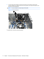
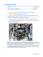
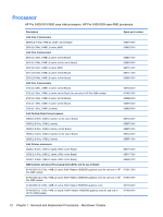
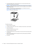
Description Spare part number X4 A6-3650 (2.6 GHz, 4-MB L2 cache, 100W; Radeon HD6550D graphics core) 667722-001 X4 A6-3620 (2.2 GHz, 4-MB L2 cache, 65W; Radeon HD6350D graphics core) 671608-001 X4 A6-3600 (2.1 GHz, 4-MB L2 cache, 65W; Radeon HD6530D graphics core) 667724-001 X4 A8-3550 (2.8 GHz, 4-MB L2 cache, 65W; Radeon HD6550D graphics core) 667721-001 X2 A4-3420 (2.8 GHz, 4-MB L2 cache, 65W; Radeon HD6530D graphics core) for use only in HP 680937-001 Pro 3505 models X2 A4-3400 (2.7 GHz, 4-MB L2 cache, 65W; Radeon HD6530D graphics core) 667725-001 X2 E2-3200 (2.4 GHz, 1-MB L2 cache, 65W; Radeon HD6370D graphics core) 667726-001 1. Prepare the computer for disassembly (Preparation for Disassembly on page 43). 2. Remove the access panel (Access Panel on page 44). 3. Lay the computer on its side with the rear facing toward you. 4. Remove the fan sink Fan Sink Assembly on page 71). 5. If removing an AMD processor, skip to step 6. If removing an Intel processor, rotate the locking lever to its full open position (1), raise and rotate the microprocessor retainer to its full open position (2), and then carefully lift the processor from the socket (3). CAUTION: Do NOT handle the pins in the processor socket. These pins are very fragile and handling them could cause irreparable damage. Once pins are damaged it may be necessary to replace the system board. CAUTION: The heat sink must be installed within 24 hours of installing the processor to prevent damage to the processor's solder connections. Figure 7-26 Removing an Intel processor Processor 73
-
 1
1 -
2
-
3
-
4
-
5
-
6
-
7
-
8
-
9
-
10
-
11
-
12
-
13
-
14
-
15
-
16
-
17
-
18
-
19
-
20
-
21
-
22
-
23
-
24
-
25
-
26
-
27
-
28
-
29
-
30
-
31
-
32
-
33
-
34
-
35
-
36
-
37
-
38
-
39
-
40
-
41
-
42
-
43
-
44
-
45
-
46
-
47
-
48
-
49
-
50
-
51
-
52
-
53
-
54
-
55
-
56
-
57
-
58
-
59
-
60
-
61
-
62
-
63
-
64
-
65
-
66
-
67
-
68
-
69
-
70
-
71
-
72
-
73
-
74
-
75
-
76
-
77
-
 78
78 -
 79
79 -
 80
80 -
 81
81 -
 82
82 -
 83
83 -
 84
84 -
 85
85 -
 86
86 -
 87
87 -
 88
88 -
89
-
90
-
91
-
92
-
93
-
94
-
95
-
96
-
97
-
98
-
99
-
100
-
101
-
102
-
103
-
104
-
105
-
106
-
107
-
108
-
109
-
110
-
111
-
112
-
113
-
114
-
115
-
116
-
117
-
118
-
119
-
120
-
121
-
122
-
123
-
124
-
125
-
126
-
127
-
128
-
129
-
130
-
131
-
132
-
133
-
134
-
135
-
136
-
137
-
138
-
139
-
140
-
141
-
142
-
143
-
144
-
145
-
146
-
147
-
148
-
149
-
150
-
151
-
152
-
153
-
154
-
155
-
156
-
157
-
158
-
159
-
160
-
161
-
162
-
163
-
164
-
165
-
166
-
167
-
168
-
169
-
170
-
171
-
172
-
173
-
174
-
175
-
176
-
177
-
178
-
179
-
180
-
181
-
182
-
183
-
184
-
185
-
186
-
187
-
188
-
189
-
190
-
191
-
192
-
193
-
194
-
195
-
196
-
197
-
198
-
199
-
200
-
201
 |
 |
