HP Pro 3500 Maintenance & Service Guide HP Pro 3400, 3405 and 3410 Microto - Page 112
Power Switch
 |
View all HP Pro 3500 manuals
Add to My Manuals
Save this manual to your list of manuals |
Page 112 highlights
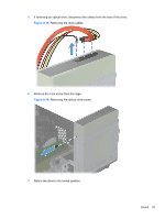
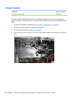
Power Switch Description Power switch/LED assembly Spare part number 656984-001 The power switch is attached to the front of the chassis using tabs (no screws). Its cable routes through metal tabs in the chassis floor. The power switch cable connects to the front USB assembly cable. 1. Prepare the computer for disassembly (Preparation for Disassembly on page 80). 2. Remove the access panel (Access Panel on page 81). 3. Remove the front bezel (Front Bezel on page 83). 4. From the inside of the computer, remove the power switch cable from the tabs on the computer floor. Figure 8-23 Removing the power switch cable 102 Chapter 8 Removal and Replacement Procedures - Small Form Factor (SFF) Chassis
-
 1
1 -
2
-
3
-
4
-
5
-
6
-
7
-
8
-
9
-
10
-
11
-
12
-
13
-
14
-
15
-
16
-
17
-
18
-
19
-
20
-
21
-
22
-
23
-
24
-
25
-
26
-
27
-
28
-
29
-
30
-
31
-
32
-
33
-
34
-
35
-
36
-
37
-
38
-
39
-
40
-
41
-
42
-
43
-
44
-
45
-
46
-
47
-
48
-
49
-
50
-
51
-
52
-
53
-
54
-
55
-
56
-
57
-
58
-
59
-
60
-
61
-
62
-
63
-
64
-
65
-
66
-
67
-
68
-
69
-
70
-
71
-
72
-
73
-
74
-
75
-
76
-
77
-
78
-
79
-
80
-
81
-
82
-
83
-
84
-
85
-
86
-
87
-
88
-
89
-
90
-
91
-
92
-
93
-
94
-
95
-
96
-
97
-
98
-
99
-
100
-
101
-
102
-
103
-
104
-
105
-
106
-
 107
107 -
 108
108 -
 109
109 -
 110
110 -
 111
111 -
 112
112 -
 113
113 -
 114
114 -
 115
115 -
 116
116 -
 117
117 -
118
-
119
-
120
-
121
-
122
-
123
-
124
-
125
-
126
-
127
-
128
-
129
-
130
-
131
-
132
-
133
-
134
-
135
-
136
-
137
-
138
-
139
-
140
-
141
-
142
-
143
-
144
-
145
-
146
-
147
-
148
-
149
-
150
-
151
-
152
-
153
-
154
-
155
-
156
-
157
-
158
-
159
-
160
-
161
-
162
-
163
-
164
-
165
-
166
-
167
-
168
-
169
-
170
-
171
-
172
-
173
-
174
-
175
-
176
-
177
-
178
-
179
-
180
-
181
-
182
-
183
-
184
-
185
-
186
-
187
-
188
-
189
-
190
-
191
-
192
-
193
-
194
-
195
-
196
-
197
-
198
-
199
-
200
-
201
 |
 |
Power Switch
Description
Spare part number
Power switch/LED assembly
656984-001
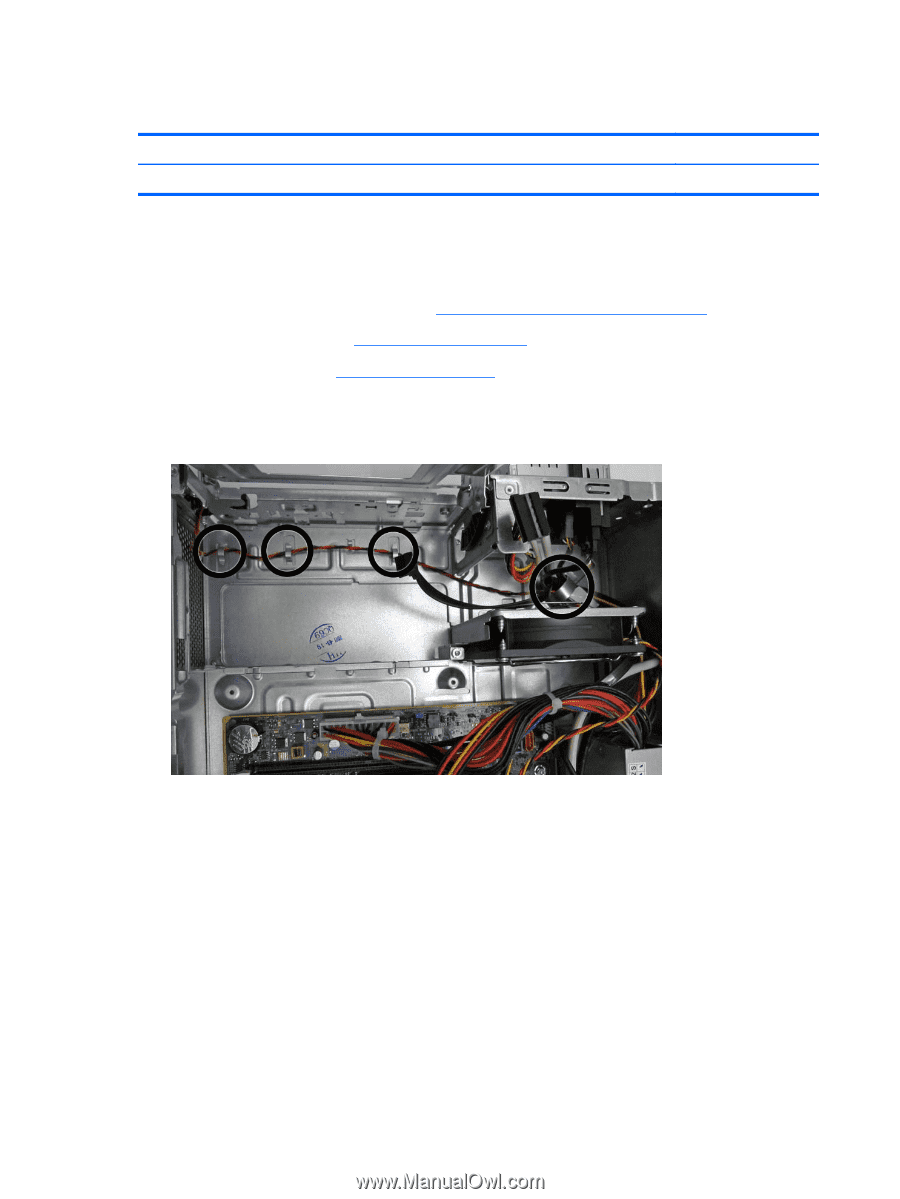
The power switch is attached to the front of the chassis using tabs (no screws). Its cable routes
through metal tabs in the chassis floor. The power switch cable connects to the front USB assembly
cable.
1.
Prepare the computer for disassembly (
Preparation for Disassembly
on page
80
).
2.
Remove the access panel (
Access Panel
on page
81
).
3.
Remove the front bezel (
Front Bezel
on page
83
).
4.
From the inside of the computer, remove the power switch cable from the tabs on the computer
floor.
Figure 8-23
Removing the power switch cable
102
Chapter 8
Removal and Replacement Procedures – Small Form Factor (SFF) Chassis