HP ProBook 4525s HP ProBook Notebook PC User Guide - Windows Vista - Page 137
on the back edge of the computer., Some models do not have any screws or screw covers to replace.
 |
View all HP ProBook 4525s manuals
Add to My Manuals
Save this manual to your list of manuals |
Page 137 highlights
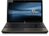
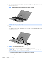
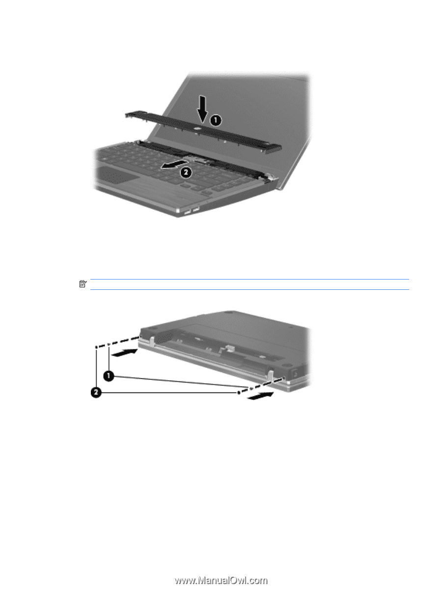
17. Place the switch cover on top of the switch cover tray (1), and then slide the switch cover into place (2). 18. Close the computer display. 19. Turn the computer upside down on a flat surface, with the battery bay toward you. 20. Replace the 2 screws (1) and their covers (2) on the back edge of the computer. NOTE: Some models do not have any screws or screw covers to replace. Adding or replacing memory modules 125
-
 1
1 -
2
-
3
-
4
-
5
-
6
-
7
-
8
-
9
-
10
-
11
-
12
-
13
-
14
-
15
-
16
-
17
-
18
-
19
-
20
-
21
-
22
-
23
-
24
-
25
-
26
-
27
-
28
-
29
-
30
-
31
-
32
-
33
-
34
-
35
-
36
-
37
-
38
-
39
-
40
-
41
-
42
-
43
-
44
-
45
-
46
-
47
-
48
-
49
-
50
-
51
-
52
-
53
-
54
-
55
-
56
-
57
-
58
-
59
-
60
-
61
-
62
-
63
-
64
-
65
-
66
-
67
-
68
-
69
-
70
-
71
-
72
-
73
-
74
-
75
-
76
-
77
-
78
-
79
-
80
-
81
-
82
-
83
-
84
-
85
-
86
-
87
-
88
-
89
-
90
-
91
-
92
-
93
-
94
-
95
-
96
-
97
-
98
-
99
-
100
-
101
-
102
-
103
-
104
-
105
-
106
-
107
-
108
-
109
-
110
-
111
-
112
-
113
-
114
-
115
-
116
-
117
-
118
-
119
-
120
-
121
-
122
-
123
-
124
-
125
-
126
-
127
-
128
-
129
-
130
-
131
-
 132
132 -
 133
133 -
 134
134 -
 135
135 -
 136
136 -
 137
137 -
 138
138 -
 139
139 -
 140
140 -
 141
141 -
 142
142 -
143
-
144
-
145
-
146
-
147
-
148
-
149
-
150
-
151
-
152
-
153
-
154
-
155
-
156
-
157
-
158
-
159
-
160
-
161
-
162
-
163
-
164
-
165
-
166
-
167
-
168
-
169
-
170
-
171
-
172
-
173
-
174
-
175
-
176
-
177
-
178
-
179
-
180
-
181
-
182
-
183
-
184
-
185
-
186
-
187
-
188
-
189
-
190
-
191
-
192
 |
 |
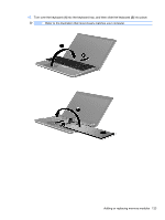
17.
Place the switch cover on top of the switch cover tray
(1)
, and then slide the switch cover into place
(2)
.
18.
Close the computer display.
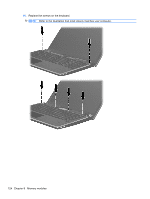
19.
Turn the computer upside down on a flat surface, with the battery bay toward you.
20.
Replace the 2 screws
(1)
and their covers
(2)
on the back edge of the computer.
NOTE:
Some models do not have any screws or screw covers to replace.
Adding or replacing memory modules
125