HP rp7440 User Service Guide, Fourth Edition - HP Integrity rx7640 and HP 9000 - Page 129
Core I/O Buttons, Core I/O Card Bulkhead LEDs, Table 5-6 Core I/O LEDs
 |
View all HP rp7440 manuals
Add to My Manuals
Save this manual to your list of manuals |
Page 129 highlights
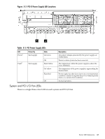
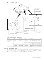
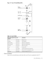
Figure 5-7 Core I/O Card Bulkhead LEDs Power Attention 10 - off 100 - on ACT/Link Locate Reset MP LAN Active MP Pwr Table 5-6 Core I/O LEDs LED (as silk-screened on the State bulkhead) Power On Green Attention On Yellow MP LAN 10 BT On Green MP LAN 100 BT On Green ACT/Link On Green Locate On Blue Reset On Amber Active On Green MP Power On Green Description I/O power on PCI attention MP LAN in 10 BT mode MP LAN in 100 BT mode MP LAN activity Locater LED Indicates that the MP is being reset This core I/O is managing the system Indicates standby power is on Core I/O Buttons There are two recessed buttons on the back of the core I/O card, as explained in Table 5-7. Server LED Indicators 129
-
 1
1 -
2
-
3
-
4
-
5
-
6
-
7
-
8
-
9
-
10
-
11
-
12
-
13
-
14
-
15
-
16
-
17
-
18
-
19
-
20
-
21
-
22
-
23
-
24
-
25
-
26
-
27
-
28
-
29
-
30
-
31
-
32
-
33
-
34
-
35
-
36
-
37
-
38
-
39
-
40
-
41
-
42
-
43
-
44
-
45
-
46
-
47
-
48
-
49
-
50
-
51
-
52
-
53
-
54
-
55
-
56
-
57
-
58
-
59
-
60
-
61
-
62
-
63
-
64
-
65
-
66
-
67
-
68
-
69
-
70
-
71
-
72
-
73
-
74
-
75
-
76
-
77
-
78
-
79
-
80
-
81
-
82
-
83
-
84
-
85
-
86
-
87
-
88
-
89
-
90
-
91
-
92
-
93
-
94
-
95
-
96
-
97
-
98
-
99
-
100
-
101
-
102
-
103
-
104
-
105
-
106
-
107
-
108
-
109
-
110
-
111
-
112
-
113
-
114
-
115
-
116
-
117
-
118
-
119
-
120
-
121
-
122
-
123
-
 124
124 -
 125
125 -
 126
126 -
 127
127 -
 128
128 -
 129
129 -
 130
130 -
 131
131 -
 132
132 -
 133
133 -
 134
134 -
135
-
136
-
137
-
138
-
139
-
140
-
141
-
142
-
143
-
144
-
145
-
146
-
147
-
148
-
149
-
150
-
151
-
152
-
153
-
154
-
155
-
156
-
157
-
158
-
159
-
160
-
161
-
162
-
163
-
164
-
165
-
166
-
167
-
168
-
169
-
170
-
171
-
172
-
173
-
174
-
175
-
176
-
177
-
178
-
179
-
180
-
181
-
182
-
183
-
184
-
185
-
186
-
187
-
188
-
189
-
190
-
191
-
192
-
193
-
194
-
195
 |
 |

Figure 5-7 Core I/O Card Bulkhead LEDs
Power
Attention
Locate
Reset
Active
MP Pwr
MP LAN
10 - off
100 - on
ACT/Link
Table 5-6 Core I/O LEDs
Description
State
LED (as silk-screened on the
bulkhead)
I/O power on
On Green
Power
PCI attention
On Yellow
Attention
MP LAN in 10 BT mode
On Green
MP LAN 10 BT
MP LAN in 100 BT mode
On Green
MP LAN 100 BT
MP LAN activity
On Green
ACT/Link
Locater LED
On Blue
Locate
Indicates that the MP is being reset
On Amber
Reset
This core I/O is managing the system
On Green
Active
Indicates standby power is on
On Green
MP Power
Core I/O Buttons
There are two recessed buttons on the back of the core I/O card, as explained in
Table 5-7
.
Server LED Indicators
129