HP rp7440 User Service Guide, Fourth Edition - HP Integrity rx7640 and HP 9000 - Page 131
PCI-X Hot-Plug LED OL* LEDs, Disk Drive LEDs, LAN Default Parameters
 |
View all HP rp7440 manuals
Add to My Manuals
Save this manual to your list of manuals |
Page 131 highlights
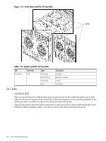
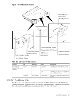
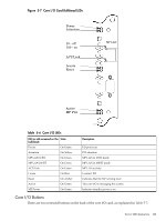
Table 5-7 Core I/O Buttons Button Identification (as Location silk-screened on the bulkhead) Function MP RESET Center of the core I/O card Resets the MP NOTE: If the MP RESET button is held for longer than five seconds, it will clear the MP password and reset the LAN, RS-232 (serial port), and modem port parameters to their default values. LAN Default Parameters • IP Address-192.168.1.1 • Subnet mask-255.255.255.0 • Default gateway-192.168.1.1 • Hostname-gsp0 RS-232 (Serial Port) Default Parameters • 9600 baud • 8 bits • No parity OLR (Symbol next to Top end of the core I/O card Request OL* for this core I/O slot button is shown below) NOTE: The OLR function is not enabled for the core I/O card. PCI-X Hot-Plug LED OL* LEDs Table 5-8 OL* LED States State Normal operation, slot power on Slot selected, slot power on Slot needs attention, slot power on Slot available, slot power off Ready for OL*, slot power off Fault detected, slot power off Slot powering down or up Power (Green) On On On Off Off Off Flashing Disk Drive LEDs There are two tri-color LED on each disk drive. Attention (Yellow) Off Flashing On Off Flashing On Off Server LED Indicators 131
-
 1
1 -
2
-
3
-
4
-
5
-
6
-
7
-
8
-
9
-
10
-
11
-
12
-
13
-
14
-
15
-
16
-
17
-
18
-
19
-
20
-
21
-
22
-
23
-
24
-
25
-
26
-
27
-
28
-
29
-
30
-
31
-
32
-
33
-
34
-
35
-
36
-
37
-
38
-
39
-
40
-
41
-
42
-
43
-
44
-
45
-
46
-
47
-
48
-
49
-
50
-
51
-
52
-
53
-
54
-
55
-
56
-
57
-
58
-
59
-
60
-
61
-
62
-
63
-
64
-
65
-
66
-
67
-
68
-
69
-
70
-
71
-
72
-
73
-
74
-
75
-
76
-
77
-
78
-
79
-
80
-
81
-
82
-
83
-
84
-
85
-
86
-
87
-
88
-
89
-
90
-
91
-
92
-
93
-
94
-
95
-
96
-
97
-
98
-
99
-
100
-
101
-
102
-
103
-
104
-
105
-
106
-
107
-
108
-
109
-
110
-
111
-
112
-
113
-
114
-
115
-
116
-
117
-
118
-
119
-
120
-
121
-
122
-
123
-
124
-
125
-
 126
126 -
 127
127 -
 128
128 -
 129
129 -
 130
130 -
 131
131 -
 132
132 -
 133
133 -
 134
134 -
 135
135 -
 136
136 -
137
-
138
-
139
-
140
-
141
-
142
-
143
-
144
-
145
-
146
-
147
-
148
-
149
-
150
-
151
-
152
-
153
-
154
-
155
-
156
-
157
-
158
-
159
-
160
-
161
-
162
-
163
-
164
-
165
-
166
-
167
-
168
-
169
-
170
-
171
-
172
-
173
-
174
-
175
-
176
-
177
-
178
-
179
-
180
-
181
-
182
-
183
-
184
-
185
-
186
-
187
-
188
-
189
-
190
-
191
-
192
-
193
-
194
-
195
 |
 |
