HP rp7440 User Service Guide, Fourth Edition - HP Integrity rx7640 and HP 9000 - Page 31
MHz/33 MHz PCI or 133 MHz/66 MHz PCI-X. Four slots in PCI-X support 266 MHz. All
 |
View all HP rp7440 manuals
Add to My Manuals
Save this manual to your list of manuals |
Page 31 highlights
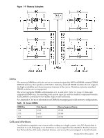
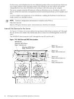
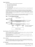
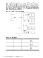
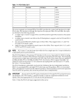
Table 1-4 PCI-X Paths Cell 1 Cell PCI-X Slot I/O Chassis Path 1 1 1 1/0/8/1 1 2 1 1/0/10/1 1 3 1 1/0/12/1 1 4 1 1/0/14/1 1 5 1 1/0/6/1 1 6 1 1/0/4/1 1 7 1 1/0/2/1 1 8 1 1/0/1/1 The server supports two internal SBAs. Each SBA provides the control and interfaces for eight PCI-X slots. The interface is through the rope bus (16 ropes per SBA). For each SBA, the ropes are divided in the following manner: • A single rope is routed to support the core I/O boards through LBAs located on the system backplane. • A single rope is routed to an LBA on the PCI backplane to support a slot for PCI and PCI-X cards (slot 8). • Six ropes are bundled into double ropes to three LBAs. They support slots 1, 2, and 7 for PCI and PCI-X mode 1 cards. • Eight fat ropes are bundled into quad ropes to four LBAs. They support slots 3, 4, 5, and 6 for PCI and PCI-X mode 2 cards. NOTE: PCI-X slots 1-7 are dual rope slots while slot 8 is a single rope slot. A rope is defined as a high speed point to point data bus. The PCI-X backplane is the primary I/O interface for the server. It provides 16, 64-bit, hot-plug PCI/PCI-X slots. Fourteen of the slots have dual ropes connected to the LBA chips. The remaining two slots have a single rope connected to each LBA chip. Each of the sixteen slots are capable of 66 MHz/33 MHz PCI or 133 MHz/66 MHz PCI-X. Four slots in PCI-X support 266 MHz. All sixteen PCI slots are keyed for 3.3 volt connectors (accepting both Universal and 3.3 V cards). See Table 1-5 for more details. The PCI-X backplane is physically one board, but it behaves like two independent partitions. SBA 0, its associated LBAs, and eight PCI-X slots form one I/O partition. SBA 1, its associated LBAs, and eight PCI-X slots form the other I/O partition. One I/O partition can be reset separately from the other I/O partition, but cannot be powered down independently. IMPORTANT: Always refer to the PCI card's manufacturer for the specific PCI card performance specifications. PCI, PCI-X mode 1, and PCI-X mode 2 cards are supported at different clock speeds. Select the appropriate PCI-X I/O slot for best performance. Table 1-5 lists the PCI-X slot types supported on the server. Detailed Server Description 31
-
 1
1 -
2
-
3
-
4
-
5
-
6
-
7
-
8
-
9
-
10
-
11
-
12
-
13
-
14
-
15
-
16
-
17
-
18
-
19
-
20
-
21
-
22
-
23
-
24
-
25
-
 26
26 -
 27
27 -
 28
28 -
 29
29 -
 30
30 -
 31
31 -
 32
32 -
 33
33 -
 34
34 -
 35
35 -
 36
36 -
37
-
38
-
39
-
40
-
41
-
42
-
43
-
44
-
45
-
46
-
47
-
48
-
49
-
50
-
51
-
52
-
53
-
54
-
55
-
56
-
57
-
58
-
59
-
60
-
61
-
62
-
63
-
64
-
65
-
66
-
67
-
68
-
69
-
70
-
71
-
72
-
73
-
74
-
75
-
76
-
77
-
78
-
79
-
80
-
81
-
82
-
83
-
84
-
85
-
86
-
87
-
88
-
89
-
90
-
91
-
92
-
93
-
94
-
95
-
96
-
97
-
98
-
99
-
100
-
101
-
102
-
103
-
104
-
105
-
106
-
107
-
108
-
109
-
110
-
111
-
112
-
113
-
114
-
115
-
116
-
117
-
118
-
119
-
120
-
121
-
122
-
123
-
124
-
125
-
126
-
127
-
128
-
129
-
130
-
131
-
132
-
133
-
134
-
135
-
136
-
137
-
138
-
139
-
140
-
141
-
142
-
143
-
144
-
145
-
146
-
147
-
148
-
149
-
150
-
151
-
152
-
153
-
154
-
155
-
156
-
157
-
158
-
159
-
160
-
161
-
162
-
163
-
164
-
165
-
166
-
167
-
168
-
169
-
170
-
171
-
172
-
173
-
174
-
175
-
176
-
177
-
178
-
179
-
180
-
181
-
182
-
183
-
184
-
185
-
186
-
187
-
188
-
189
-
190
-
191
-
192
-
193
-
194
-
195
 |
 |
