HP rp7440 User Service Guide, Fourth Edition - HP Integrity rx7640 and HP 9000 - Page 24
Cell Board, Front Panel LEDs and Power Switch, Cell Board
 |
View all HP rp7440 manuals
Add to My Manuals
Save this manual to your list of manuals |
Page 24 highlights
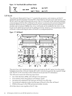
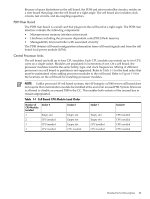
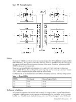
Figure 1-6 Front Panel LEDs and Power Switch Cell Board The cell board, illustrated in Figure 1-7, contains the processors, main memory, and the CC application specific integrated circuit (ASIC) which interfaces the processors and memory with the I/O, and to the other cell board in the server. The CC is the heart of the cell board, enabling communication with the other cell board in the system. It connects to the processor dependent hardware (PDH) and micro controller hardware. Each cell board holds up to two processor modules and 16 memory DIMMs. One or two cell boards can be installed in the server. A cell board can be selectively powered off for adding processors, memory, or for maintenance of the cell board, without affecting the other cell board in a configured partition. Figure 1-7 Cell Board The server has a 48 V distributed power system and receives the 48 V power from the system backplane board. The cell board contains DC-to-DC converters to generate the required voltage rails. The DC-to-DC converters on the cell board do not provide N+1 redundancy. The cell board contains the following major buses: • Two front side buses (FSB), each with up to two processors • Four memory buses (one going to each memory quad) • Incoming and outgoing I/O bus that goes off board to an SBA chip • Incoming and outgoing crossbar bus that goes off board to the other cell board • PDH bus that goes to the PDH and microcontroller circuitry All of these buses come together at the CC chip. 24 HP Integrity rx7640 Server and HP 9000 rp7440 Server Overview
-
 1
1 -
2
-
3
-
4
-
5
-
6
-
7
-
8
-
9
-
10
-
11
-
12
-
13
-
14
-
15
-
16
-
17
-
18
-
 19
19 -
 20
20 -
 21
21 -
 22
22 -
 23
23 -
 24
24 -
 25
25 -
 26
26 -
 27
27 -
 28
28 -
 29
29 -
30
-
31
-
32
-
33
-
34
-
35
-
36
-
37
-
38
-
39
-
40
-
41
-
42
-
43
-
44
-
45
-
46
-
47
-
48
-
49
-
50
-
51
-
52
-
53
-
54
-
55
-
56
-
57
-
58
-
59
-
60
-
61
-
62
-
63
-
64
-
65
-
66
-
67
-
68
-
69
-
70
-
71
-
72
-
73
-
74
-
75
-
76
-
77
-
78
-
79
-
80
-
81
-
82
-
83
-
84
-
85
-
86
-
87
-
88
-
89
-
90
-
91
-
92
-
93
-
94
-
95
-
96
-
97
-
98
-
99
-
100
-
101
-
102
-
103
-
104
-
105
-
106
-
107
-
108
-
109
-
110
-
111
-
112
-
113
-
114
-
115
-
116
-
117
-
118
-
119
-
120
-
121
-
122
-
123
-
124
-
125
-
126
-
127
-
128
-
129
-
130
-
131
-
132
-
133
-
134
-
135
-
136
-
137
-
138
-
139
-
140
-
141
-
142
-
143
-
144
-
145
-
146
-
147
-
148
-
149
-
150
-
151
-
152
-
153
-
154
-
155
-
156
-
157
-
158
-
159
-
160
-
161
-
162
-
163
-
164
-
165
-
166
-
167
-
168
-
169
-
170
-
171
-
172
-
173
-
174
-
175
-
176
-
177
-
178
-
179
-
180
-
181
-
182
-
183
-
184
-
185
-
186
-
187
-
188
-
189
-
190
-
191
-
192
-
193
-
194
-
195
 |
 |
