IBM 326m Hardware Maintenance Manual - Page 48
power-cord
 |
UPC - 000435835093
View all IBM 326m manuals
Add to My Manuals
Save this manual to your list of manuals |
Page 48 highlights
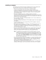
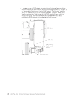
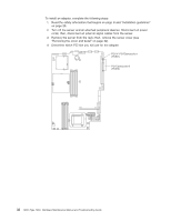
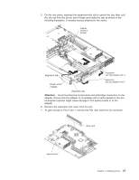
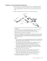
8. To gain access to PCI Express slot 2, remove the power-cord module. a. Press down on the retention clip at the front of the power-cord module and slide the module toward the front of the server until the alignment tab is free of the slot on the side of the server. b. Lift and place the power-cord module out of the server as far as the power supply cable permits. 9. Install the adapter: Attention: When you handle static-sensitive devices, take precautions to avoid damage from static electricity. For information about handling these devices, see "Handling static-sensitive devices" on page 30. a. Remove the adapter from the static-protective package and set any jumpers or switches on the adapter as directed by the adapter manufacturer. If you are installing a full-length adapter, you might have to remove a plastic bracket secured to the adapter with 2 screws before installing the adapter. Attention: When you install an adapter, make sure that the adapter is correctly seated in the connector before you turn on the server. Improperly seated adapters might cause damage to the system board, the riser card, or the adapter. b. If you are installing an adapter in PCI-X slot 1, attach the PCI riser card to the adapter. Reinstall the PCI riser card with the adapter already attached to the PCI riser card. c. Grasp the adapter by its top edge or upper corners, align it with the connector, and press it firmly into the connector. 10. Slide the expansion-slot clip toward the server until it snaps into place to secure the adapter in the adapter slot. 11. Connect any internal cables to the adapter. See the instructions that come with the adapter for details. Attention: Make sure that the cables do not block the flow of air from the fans. 12. If you removed the power-cord module to install the adapter in PCI Express slot 2, install the module by reversing the procedure in step 8a. Ensure that the alignment tab is fully seated in the slot on the side of the server. 38 326m Type 7969: Hardware Maintenance Manual and Troubleshooting Guide
-
 1
1 -
2
-
3
-
4
-
5
-
6
-
7
-
8
-
9
-
10
-
11
-
12
-
13
-
14
-
15
-
16
-
17
-
18
-
19
-
20
-
21
-
22
-
23
-
24
-
25
-
26
-
27
-
28
-
29
-
30
-
31
-
32
-
33
-
34
-
35
-
36
-
37
-
38
-
39
-
40
-
41
-
42
-
 43
43 -
 44
44 -
 45
45 -
 46
46 -
 47
47 -
 48
48 -
 49
49 -
 50
50 -
 51
51 -
 52
52 -
 53
53 -
54
-
55
-
56
-
57
-
58
-
59
-
60
-
61
-
62
-
63
-
64
-
65
-
66
-
67
-
68
-
69
-
70
-
71
-
72
-
73
-
74
-
75
-
76
-
77
-
78
-
79
-
80
-
81
-
82
-
83
-
84
-
85
-
86
-
87
-
88
-
89
-
90
-
91
-
92
-
93
-
94
-
95
-
96
-
97
-
98
-
99
-
100
-
101
-
102
-
103
-
104
-
105
-
106
-
107
-
108
-
109
-
110
-
111
-
112
-
113
-
114
-
115
-
116
-
117
-
118
-
119
-
120
-
121
-
122
-
123
-
124
-
125
-
126
-
127
-
128
-
129
-
130
-
131
-
132
-
133
-
134
-
135
-
136
-
137
-
138
-
139
-
140
-
141
-
142
-
143
-
144
-
145
-
146
-
147
-
148
-
149
-
150
-
151
-
152
-
153
-
154
-
155
-
156
-
157
-
158
-
159
-
160
-
161
-
162
-
163
-
164
-
165
-
166
-
167
-
168
-
169
-
170
-
171
-
172
 |
 |
