IBM 326m Hardware Maintenance Manual - Page 85
Removing, system, board
 |
UPC - 000435835093
View all IBM 326m manuals
Add to My Manuals
Save this manual to your list of manuals |
Page 85 highlights
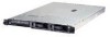
Removing the system board Complete the following steps to remove the system board. Note: v Read "Installation guidelines" on page 29. v Read the safety notices at "Safety information" on page 107. v Read "Handling static-sensitive devices" on page 30. 1. Turn off the server and any attached devices. Note: When replacing the system board, you must either update the server with the latest firmware or restore the pre-existing firmware that the customer provides on a diskette or CD image. 2. Disconnect power cords and external cables from the back of the server. 3. Remove the server from the rack. 4. Remove the cover (see "Removing the cover and bezel" on page 32). 5. Remove all adapters (see "Installing an adapter" on page 33). 6. Remove all fans (see "Replacing a fan assembly" on page 50). 7. Remove the air baffle. 8. Remove the riser card (see "Riser card" on page 67). 9. Remove the screw securing the PCI adapter shield in position, and remove the PCI adapter shield, making sure to put them in a safe place for reinstallation. 10. Remove the SCSI backplane (see "SCSI backplane" on page 66). 11. Disconnect all cables from the system board. 12. Remove the heat sinks from all the microprocessors and set them aside on a static-protected surface for reinstallation (see "Installing an additional microprocessor" on page 44). 13. Remove all microprocessors and set them aside on a static-protected surface for reinstallation (see "Installing an additional microprocessor" on page 44). 14. Remove the memory modules and set them aside on a static-protected surface for reinstallation (see "Installing a memory module" on page 42). Note: The illustrations in this document might differ slightly from your hardware. Chapter 6. Service replaceable units 75
-
 1
1 -
2
-
3
-
4
-
5
-
6
-
7
-
8
-
9
-
10
-
11
-
12
-
13
-
14
-
15
-
16
-
17
-
18
-
19
-
20
-
21
-
22
-
23
-
24
-
25
-
26
-
27
-
28
-
29
-
30
-
31
-
32
-
33
-
34
-
35
-
36
-
37
-
38
-
39
-
40
-
41
-
42
-
43
-
44
-
45
-
46
-
47
-
48
-
49
-
50
-
51
-
52
-
53
-
54
-
55
-
56
-
57
-
58
-
59
-
60
-
61
-
62
-
63
-
64
-
65
-
66
-
67
-
68
-
69
-
70
-
71
-
72
-
73
-
74
-
75
-
76
-
77
-
78
-
79
-
 80
80 -
 81
81 -
 82
82 -
 83
83 -
 84
84 -
 85
85 -
 86
86 -
 87
87 -
 88
88 -
 89
89 -
 90
90 -
91
-
92
-
93
-
94
-
95
-
96
-
97
-
98
-
99
-
100
-
101
-
102
-
103
-
104
-
105
-
106
-
107
-
108
-
109
-
110
-
111
-
112
-
113
-
114
-
115
-
116
-
117
-
118
-
119
-
120
-
121
-
122
-
123
-
124
-
125
-
126
-
127
-
128
-
129
-
130
-
131
-
132
-
133
-
134
-
135
-
136
-
137
-
138
-
139
-
140
-
141
-
142
-
143
-
144
-
145
-
146
-
147
-
148
-
149
-
150
-
151
-
152
-
153
-
154
-
155
-
156
-
157
-
158
-
159
-
160
-
161
-
162
-
163
-
164
-
165
-
166
-
167
-
168
-
169
-
170
-
171
-
172
 |
 |
