IBM 326m Hardware Maintenance Manual - Page 56
Aunpainted
 |
UPC - 000435835093
View all IBM 326m manuals
Add to My Manuals
Save this manual to your list of manuals |
Page 56 highlights
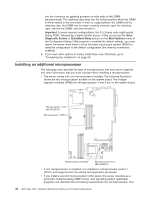
5. Install the microprocessor: a. Touch the static-protective package containing the new microprocessor to any unpainted metal surface on the server; then, remove the microprocessor from the package. b. Position the microprocessor over the microprocessor socket as shown in the following illustration. Carefully press the microprocessor into the socket. Attention: To avoid bending the pins on the microprocessor, do not use excessive force when pressing it into the socket. Microprocessor Microprocessor orientation indicator Microprocessorlocking lever Microprocessor socket 6. Close the microprocessor-locking lever to secure the microprocessor. Note: A new microprocessor comes in a kit with a heat sink. 7. Install the heat sink. Attention: Do not disturb or contaminate the thermal material on the bottom of the new heat sink. Doing so damages its heat-conducting capability and exposes the new microprocessor to overheating. a. Remove the heat sink from its package and remove the cover from the bottom of the heat sink. b. Make sure that the thermal material is still on the bottom of the heat sink, and position the heat sink on top of the microprocessor. c. Align the captive screws on the heat sink with the holes on the heat-sink retention module. d. Press firmly on the captive screws and tighten them, alternating between screws until they are tight. Do not overtighten the screws by using excessive force. Attention: If you need to remove the heat sink after installing it, note that the thermal material might have formed a strong bond between the heat sink and the microprocessor. Do not force the heat sink and microprocessor apart; doing so can damage the microprocessor pins. Loosening one captive screw fully before loosening the other captive screw helps break the bond between the components without damaging them. 46 326m Type 7969: Hardware Maintenance Manual and Troubleshooting Guide
-
 1
1 -
2
-
3
-
4
-
5
-
6
-
7
-
8
-
9
-
10
-
11
-
12
-
13
-
14
-
15
-
16
-
17
-
18
-
19
-
20
-
21
-
22
-
23
-
24
-
25
-
26
-
27
-
28
-
29
-
30
-
31
-
32
-
33
-
34
-
35
-
36
-
37
-
38
-
39
-
40
-
41
-
42
-
43
-
44
-
45
-
46
-
47
-
48
-
49
-
50
-
 51
51 -
 52
52 -
 53
53 -
 54
54 -
 55
55 -
 56
56 -
 57
57 -
 58
58 -
 59
59 -
 60
60 -
 61
61 -
62
-
63
-
64
-
65
-
66
-
67
-
68
-
69
-
70
-
71
-
72
-
73
-
74
-
75
-
76
-
77
-
78
-
79
-
80
-
81
-
82
-
83
-
84
-
85
-
86
-
87
-
88
-
89
-
90
-
91
-
92
-
93
-
94
-
95
-
96
-
97
-
98
-
99
-
100
-
101
-
102
-
103
-
104
-
105
-
106
-
107
-
108
-
109
-
110
-
111
-
112
-
113
-
114
-
115
-
116
-
117
-
118
-
119
-
120
-
121
-
122
-
123
-
124
-
125
-
126
-
127
-
128
-
129
-
130
-
131
-
132
-
133
-
134
-
135
-
136
-
137
-
138
-
139
-
140
-
141
-
142
-
143
-
144
-
145
-
146
-
147
-
148
-
149
-
150
-
151
-
152
-
153
-
154
-
155
-
156
-
157
-
158
-
159
-
160
-
161
-
162
-
163
-
164
-
165
-
166
-
167
-
168
-
169
-
170
-
171
-
172
 |
 |
