IBM 326m Hardware Maintenance Manual - Page 53
connector.
 |
UPC - 000435835093
View all IBM 326m manuals
Add to My Manuals
Save this manual to your list of manuals |
Page 53 highlights
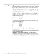
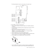
The following illustration shows the memory slots on the system board. DIMM 4 (DDR4) DIMM 3 (DDR3) DIMM 2 (DDR2) DIMM 1 (DDR1) DIMM 8 (DDR8) DIMM 7 (DDR7) DIMM 6 (DDR6) DIMM 5 (DDR5) To install DIMMs, complete the following steps: 1. Read the safety information that begins on page iii and "Installation guidelines" on page 29. 2. Turn off the server and peripheral devices, and disconnect the power cords and all external cables. 3. Remove the server from the rack; then, remove the server cover (see "Removing the cover and bezel" on page 32). Attention: To avoid breaking the retaining clips or damaging the DIMM connectors, open and close the clips gently. 4. Open the retaining clip on each end of the DIMM connector. 5. Touch the static-protective package containing the DIMM to any unpainted metal surface on the server. Then, remove the DIMM from the package. 6. Turn the DIMM so that the DIMM keys align correctly with the slot. 7. Insert the DIMM into the connector by aligning the edges of the DIMM with the slots at the ends of the DIMM connector. Firmly press the DIMM straight down Chapter 4. Installing options 43
-
 1
1 -
2
-
3
-
4
-
5
-
6
-
7
-
8
-
9
-
10
-
11
-
12
-
13
-
14
-
15
-
16
-
17
-
18
-
19
-
20
-
21
-
22
-
23
-
24
-
25
-
26
-
27
-
28
-
29
-
30
-
31
-
32
-
33
-
34
-
35
-
36
-
37
-
38
-
39
-
40
-
41
-
42
-
43
-
44
-
45
-
46
-
47
-
 48
48 -
 49
49 -
 50
50 -
 51
51 -
 52
52 -
 53
53 -
 54
54 -
 55
55 -
 56
56 -
 57
57 -
 58
58 -
59
-
60
-
61
-
62
-
63
-
64
-
65
-
66
-
67
-
68
-
69
-
70
-
71
-
72
-
73
-
74
-
75
-
76
-
77
-
78
-
79
-
80
-
81
-
82
-
83
-
84
-
85
-
86
-
87
-
88
-
89
-
90
-
91
-
92
-
93
-
94
-
95
-
96
-
97
-
98
-
99
-
100
-
101
-
102
-
103
-
104
-
105
-
106
-
107
-
108
-
109
-
110
-
111
-
112
-
113
-
114
-
115
-
116
-
117
-
118
-
119
-
120
-
121
-
122
-
123
-
124
-
125
-
126
-
127
-
128
-
129
-
130
-
131
-
132
-
133
-
134
-
135
-
136
-
137
-
138
-
139
-
140
-
141
-
142
-
143
-
144
-
145
-
146
-
147
-
148
-
149
-
150
-
151
-
152
-
153
-
154
-
155
-
156
-
157
-
158
-
159
-
160
-
161
-
162
-
163
-
164
-
165
-
166
-
167
-
168
-
169
-
170
-
171
-
172
 |
 |
