IBM 326m Hardware Maintenance Manual - Page 54
Installing, additional, microprocessor
 |
UPC - 000435835093
View all IBM 326m manuals
Add to My Manuals
Save this manual to your list of manuals |
Page 54 highlights
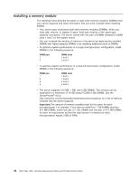
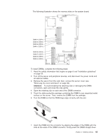
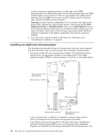
into the connector by applying pressure on both ends of the DIMM simultaneously. The retaining clips snap into the locked position when the DIMM is firmly seated in the connector. If there is a gap between the DIMM and the retaining clips, the DIMM has not been correctly inserted; open the retaining clips, remove the DIMM, and then reinsert it. Important: In some memory configurations, the 3-3-3 beep code might sound during POST, followed by a blank monitor screen. If this occurs and the Boot Diagnostic Screen or QuickBoot Mode feature on the Start Options menu of the Configuration/Setup Utility program is enabled (its default setting), you must restart the server three times to force the basic input/output system (BIOS) to reset the configuration to the default configuration (the memory connectors enabled). 8. If you have other options to install, install them now. Otherwise, go to "Completing the installation" on page 53. Installing an additional microprocessor The following notes describe the type of microprocessor that your server supports and other information that you must consider when installing a microprocessor: v The server comes with one microprocessor installed. The following illustration shows the two microprocessor sockets on the system board. The voltage regulator modules (VRMs) for microprocessors 1 and 2 are on the system board. Microprocessor 1 error LED (DLED13) Microprocessor 1 (CPU1) Microprocessor 2 (CPU2) Microprocessor 2 error LED (DLED14) v If one microprocessor is installed, it is installed in microprocessor socket 1 (CPU1) and supports both the startup and application processes. v If you install a second microprocessor in the server, the server operates as a symmetric multiprocessing (SMP) server, and operating-system application programs can distribute the processing load between the microprocessors. This 44 326m Type 7969: Hardware Maintenance Manual and Troubleshooting Guide
-
 1
1 -
2
-
3
-
4
-
5
-
6
-
7
-
8
-
9
-
10
-
11
-
12
-
13
-
14
-
15
-
16
-
17
-
18
-
19
-
20
-
21
-
22
-
23
-
24
-
25
-
26
-
27
-
28
-
29
-
30
-
31
-
32
-
33
-
34
-
35
-
36
-
37
-
38
-
39
-
40
-
41
-
42
-
43
-
44
-
45
-
46
-
47
-
48
-
 49
49 -
 50
50 -
 51
51 -
 52
52 -
 53
53 -
 54
54 -
 55
55 -
 56
56 -
 57
57 -
 58
58 -
 59
59 -
60
-
61
-
62
-
63
-
64
-
65
-
66
-
67
-
68
-
69
-
70
-
71
-
72
-
73
-
74
-
75
-
76
-
77
-
78
-
79
-
80
-
81
-
82
-
83
-
84
-
85
-
86
-
87
-
88
-
89
-
90
-
91
-
92
-
93
-
94
-
95
-
96
-
97
-
98
-
99
-
100
-
101
-
102
-
103
-
104
-
105
-
106
-
107
-
108
-
109
-
110
-
111
-
112
-
113
-
114
-
115
-
116
-
117
-
118
-
119
-
120
-
121
-
122
-
123
-
124
-
125
-
126
-
127
-
128
-
129
-
130
-
131
-
132
-
133
-
134
-
135
-
136
-
137
-
138
-
139
-
140
-
141
-
142
-
143
-
144
-
145
-
146
-
147
-
148
-
149
-
150
-
151
-
152
-
153
-
154
-
155
-
156
-
157
-
158
-
159
-
160
-
161
-
162
-
163
-
164
-
165
-
166
-
167
-
168
-
169
-
170
-
171
-
172
 |
 |
