Intel SBXD132 User Guide - Page 20
Blade Server Connectors, Information LED, Blade-error LED, Power-control button, Power-on LED
 |
UPC - 735858189408
View all Intel SBXD132 manuals
Add to My Manuals
Save this manual to your list of manuals |
Page 20 highlights
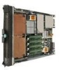
Information LED: When this amber LED is lit, it indicates that information about a system error for the blade server has been placed in the management-module event log. The information LED can be turned off through the management-module Web interface. Blade-error LED: When this amber LED is lit, it indicates that a system error has occurred in the blade server. The blade-error LED will turn off only after the error is corrected. Power-control button: This button is behind the control panel door. Press this button to turn on or turn off the blade server. Note: The power-control button has effect only if local power control is enabled for the blade server. Local power control is enabled and disabled through the management-module Web interface. Power-on LED: This green LED indicates the power status of the blade server in the following manner: • Flashing rapidly: The service processor (BMC) on the blade server is communicating with the management module. • Flashing slowly: The blade server has power but is not turned on. • Lit continuously: The blade server has power and is turned on. Blade Server Connectors The following illustration shows the system-board components, including connectors for user-installable options, for the blade server. Blade-expansion option (J132) DIMM 4 (J144) DIMM 3 (J143) DIMM 2 (J142) DIMM 1 (J141) I/O-expansion option (J134) I/O-expansion option (J131) SAS hard disk drive 1 (J137) SAS hard disk drive 0 (J136) Battery (BH1) Microprocessor 1 (U66) Microprocessor 2 (U70) Control panel connector (J155) Power connector (J164) Memory connector (J150) AF002051 12 Intel® Server Compute Blade SBXD132 Installation and User's Guide
-
 1
1 -
2
-
3
-
4
-
5
-
6
-
7
-
8
-
9
-
10
-
11
-
12
-
13
-
14
-
 15
15 -
 16
16 -
 17
17 -
 18
18 -
 19
19 -
 20
20 -
 21
21 -
 22
22 -
 23
23 -
 24
24 -
 25
25 -
26
-
27
-
28
-
29
-
30
-
31
-
32
-
33
-
34
-
35
-
36
-
37
-
38
-
39
-
40
-
41
-
42
-
43
-
44
-
45
-
46
-
47
-
48
-
49
-
50
-
51
-
52
-
53
-
54
-
55
-
56
-
57
-
58
-
59
-
60
-
61
-
62
-
63
-
64
-
65
-
66
-
67
-
68
-
69
-
70
-
71
-
72
-
73
-
74
-
75
-
76
-
77
-
78
-
79
-
80
-
81
-
82
-
83
-
84
-
85
-
86
-
87
-
88
-
89
-
90
-
91
-
92
-
93
-
94
-
95
-
96
-
97
-
98
-
99
-
100
-
101
-
102
-
103
-
104
-
105
-
106
-
107
-
108
-
109
-
110
-
111
-
112
-
113
-
114
-
115
-
116
-
117
-
118
-
119
-
120
-
121
-
122
-
123
-
124
-
125
-
126
-
127
-
128
-
129
-
130
 |
 |
