Intel SBXD132 User Guide - Page 55
To avoid breaking the retaining clips or damaging the controller socket
 |
UPC - 735858189408
View all Intel SBXD132 manuals
Add to My Manuals
Save this manual to your list of manuals |
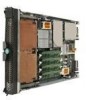
Page 55 highlights
Caution: To avoid breaking the retaining clips or damaging the controller socket, open and close the clips gently. 8. Insert the SAS controller by pressing it along the guides into the connector socket. Make sure that the retaining clips snap into the closed position. 9. If you have I/O-expansion cards to install in the expansion unit, do so now (see "Installing an I/O-expansion Card" on page 47); otherwise, go to "Completing the Installation" on page 51. Installing an I/O-expansion Card You can install up to two I/O-expansion cards in the expansion unit to provide additional connections for communicating on a network. The following illustration shows the locations of the connectors and the different form factors of the supported I/O-expansion cards in the expansion unit. Shared I/O-expansion connectors A B Blade expansion A B connector Shared I/O-expansion connectors AF000939 Before installing an I/O-expansion card, consider the following information: • The expansion unit supports two different form factors of I/O-expansion cards: standard form factor (A) and small form factor (B). • Either a standard-form-factor or a small-form-factor card can be installed in each pair of the shared connectors, (1 and 2). • The network-interface type of the I/O-expansion card must be supported by the corresponding I/O modules in the SBCE unit. - Connector 1 provides a connection to SBCE unit I/O bays 1 and 2. - Connector 2 provides a connection to SBCE unit I/O bays 3 and 4. To install an I/O-expansion card, complete the following steps: 1. Read the Safety information beginning on page vii and "Installation Guidelines" on page 39. 2. If the host blade server and expansion unit are installed in a SBCE unit, complete the following steps: Intel® Server Compute Blade SBXD132 Installation and User's Guide 47
-
 1
1 -
2
-
3
-
4
-
5
-
6
-
7
-
8
-
9
-
10
-
11
-
12
-
13
-
14
-
15
-
16
-
17
-
18
-
19
-
20
-
21
-
22
-
23
-
24
-
25
-
26
-
27
-
28
-
29
-
30
-
31
-
32
-
33
-
34
-
35
-
36
-
37
-
38
-
39
-
40
-
41
-
42
-
43
-
44
-
45
-
46
-
47
-
48
-
49
-
 50
50 -
 51
51 -
 52
52 -
 53
53 -
 54
54 -
 55
55 -
 56
56 -
 57
57 -
 58
58 -
 59
59 -
 60
60 -
61
-
62
-
63
-
64
-
65
-
66
-
67
-
68
-
69
-
70
-
71
-
72
-
73
-
74
-
75
-
76
-
77
-
78
-
79
-
80
-
81
-
82
-
83
-
84
-
85
-
86
-
87
-
88
-
89
-
90
-
91
-
92
-
93
-
94
-
95
-
96
-
97
-
98
-
99
-
100
-
101
-
102
-
103
-
104
-
105
-
106
-
107
-
108
-
109
-
110
-
111
-
112
-
113
-
114
-
115
-
116
-
117
-
118
-
119
-
120
-
121
-
122
-
123
-
124
-
125
-
126
-
127
-
128
-
129
-
130
 |
 |
