Intel SBXD132 User Guide - Page 40
Completing the Installation, the Memory and I/O Expansion Blade.
 |
UPC - 735858189408
View all Intel SBXD132 manuals
Add to My Manuals
Save this manual to your list of manuals |
Page 40 highlights
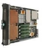
3. Remove the protective covers from the blade expansion connectors, if they are present. Note: For some expansion units, you only need to remove the cover closest to the rear of the blade server. 4. If you are installing a Memory and I/O Expansion Blade on the blade server, remove the power jumper from power connector J164. Store the power jumper in a safe place. 5. Touch the static-protective package that contains the expansion unit to any unpainted metal surface on the SBCE unit or any unpainted metal surface on any other grounded rack component; then, remove the expansion unit from the package. 6. Install the expansion unit: a. Orient the expansion unit as shown in the illustration. b. Lower the expansion unit so that the slots at the rear slide down onto the cover pins at the rear of the blade server. c. Close the expansion unit (see the documentation for the expansion unit for information and instructions): -- If the expansion unit has an extraction device, pivot the expansion unit closed; then, use the extraction device to fully seat the expansion unit on the system board. These extraction devices can be of several types, including thumb screws or levers. -- If the expansion unit has no extraction device, pivot the expansion unit closed; then, press the expansion unit firmly into place until the blade-cover releases click. The connectors on the expansion unit automatically align with and connect to the connectors on the system board. 7. If you have other expansion units to install, do so now; otherwise, go to "Completing the Installation" on page 32. Completing the Installation To complete the installation, complete the following tasks. Instructions for each task are in the following sections. 1. Reinstall the blade server bezel assembly, if you removed it (see "Installing the Blade Server Bezel Assembly" on page 33 for information on installing the bezel assembly). 2. Reinstall the Memory and I/O Expansion Blade, if you removed it to install other options (see "Installing an Expansion Unit" on page 31 for information on installing the Memory and I/O Expansion Blade). 3. Close the blade server cover, unless you installed an optional expansion unit that has its own cover (see "Closing the Blade Server Cover" on page 34). 32 Intel® Server Compute Blade SBXD132 Installation and User's Guide
-
 1
1 -
2
-
3
-
4
-
5
-
6
-
7
-
8
-
9
-
10
-
11
-
12
-
13
-
14
-
15
-
16
-
17
-
18
-
19
-
20
-
21
-
22
-
23
-
24
-
25
-
26
-
27
-
28
-
29
-
30
-
31
-
32
-
33
-
34
-
 35
35 -
 36
36 -
 37
37 -
 38
38 -
 39
39 -
 40
40 -
 41
41 -
 42
42 -
 43
43 -
 44
44 -
 45
45 -
46
-
47
-
48
-
49
-
50
-
51
-
52
-
53
-
54
-
55
-
56
-
57
-
58
-
59
-
60
-
61
-
62
-
63
-
64
-
65
-
66
-
67
-
68
-
69
-
70
-
71
-
72
-
73
-
74
-
75
-
76
-
77
-
78
-
79
-
80
-
81
-
82
-
83
-
84
-
85
-
86
-
87
-
88
-
89
-
90
-
91
-
92
-
93
-
94
-
95
-
96
-
97
-
98
-
99
-
100
-
101
-
102
-
103
-
104
-
105
-
106
-
107
-
108
-
109
-
110
-
111
-
112
-
113
-
114
-
115
-
116
-
117
-
118
-
119
-
120
-
121
-
122
-
123
-
124
-
125
-
126
-
127
-
128
-
129
-
130
 |
 |
