JVC BR-DV6000U User Manual
JVC BR-DV6000U - Advanced Professional DV Recorder Manual
 |
UPC - 046838325557
View all JVC BR-DV6000U manuals
Add to My Manuals
Save this manual to your list of manuals |
JVC BR-DV6000U manual content summary:
- JVC BR-DV6000U | User Manual - Page 1
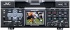
DV VIDEO CASSETTE RECORDER BR-DV6000U INSTRUCTION MANUAL Mini MENU DISP RESET SEARCH- SET SEARCH+ MIC HOLD BLANK CUE UP PHONES REC LEVEL CH-1/3 CH-2/4 PROFESSIONAL BR-DV6000 OPERATE A.DUB REC PLAY PAUSE EJECT REW STOP FF AUDIO INPUT COUNTER MONITOR OUTPUT SELECT CTL L CH-1/2 - JVC BR-DV6000U | User Manual - Page 2
of power supplied to your home, consult your dealer or local power company. For appliance designed to operate from battery power, refer to the operating instructions. need for service. 18. When replacement parts are required, be sure the service technician has used replacement parts specified by - JVC BR-DV6000U | User Manual - Page 3
identification (numéro de série) se trouve sur le panneau arrière de l'appareil. WARNING: The battery used in the BR-DV6000U must be replaced by a JVC authorized service dealer only. This digital apparatus does not exceed the Class B limits for radio noise emissions from digital apparatus as set out - JVC BR-DV6000U | User Manual - Page 4
without the prior consent of the copyright owner. ● JVC shall not guarantee the quality of recording and playback should BR-DV6000 fail to function normally due to defects, either of the unit itself or the video cassette tapes. MAIN FEATURES ● DV format High picture and sound quality by digital - JVC BR-DV6000U | User Manual - Page 5
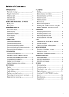
34 Connecting the AC adapter 35 PREPARATION Turning on/off the power 36 Operation method (main unit/remote controller) and operation lock mode 37 Loading/Ejecting cassette 38 Setting the LCD display 39 Setting/Displaying date and time 40 RECORDING Setting 42 Recording procedure 43 Audio - JVC BR-DV6000U | User Manual - Page 6
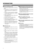
or using this VCR in the cassette tape from the cassette slot when transporting the unit. ● Remove the AC adapter to save energy when the unit is not in use. Ⅵ Maintaining the unit (Turn off the power Use the supplied AC adapter to connect the unit to a power source. Ⅵ Use the supplied power cord. - JVC BR-DV6000U | User Manual - Page 7
as a guide. Usage Time Maintenance consultation : You can check the drum usage time with the hour meter display. For details, refer to page 100, "Checking the hour meter." : For details on the maintenance plan and fee, consult with your JVC-authorized service agent. Ⅵ Head cleaning • Recording or - JVC BR-DV6000U | User Manual - Page 8
˚C 1 to 2 times every 5 hours Cassette tape BR-DV6000 can record onto and playback standard DV and mini DV cassette tapes (for SP mode only). Use the following JVC cassettes with the or the logo. ● Standard DV cassettes LA-DV276 LA-DV186 LA-DV124 ● Mini DV cassettes M-DV63PRO M-DV60 M-DV30 Memo - JVC BR-DV6000U | User Manual - Page 9
CONDENSATION ON DRUM Leave the unit with the power ON and wait until the WARNING message disappears. • Prevention of condensation When transporting BR-DV6000 from a cold to a warmer place abruptly, first remove the cassette tape. Then place BR-DV6000 in a plastic bag and seal it before transporting - JVC BR-DV6000U | User Manual - Page 10
even if this button is not pressed. ● Even after the power is turned off with this button, BR-DV6000 is live with a small amount of electricity. Therefore, if BR-DV6000 is not to be used for a long period of time, please remove the AC adapter to save energy. 10 3 Operation buttons Ⅵ [A. DUB] Audio - JVC BR-DV6000U | User Manual - Page 11
mode. In the RECORDING PAUSE or STILL mode, the green LED lights up. • When BR-DV6000 is in the STILL cassette. Memo ● It takes about 6 seconds for the cassette to be ejected. ● The cassette can be ejected even when BRDV6000 is in the OPERATE OFF mode. After the eject action is completed, BR-DV6000 - JVC BR-DV6000U | User Manual - Page 12
REMOTE SEL 9 PIN while the 12-PIN REMOTE 2 Note Switching is invalid during recording. terminal can be selected with RE- MOTE SEL JVC. 6 [AUDIO OUTPUT] switch Memo ● To control BR-DV6000 with the SERIAL REMOTE terminal or DV terminal, this switch setting can be set up with REMOTE SEL SERIAL or - JVC BR-DV6000U | User Manual - Page 13
in combi- nation, the AUDIO MONITOR OUT outputs the sounds listed as in the following table. • During playback of tapes recorded in the 32 K audio mode • In the EE mode for DV input in the 32 K audio mode • During audio dubbing AUDIO switch MONITOR OUTPUT CH-1/2 L MIX CH-3/4 CH-1/2 MIX MIX - JVC BR-DV6000U | User Manual - Page 14
REC LEVEL CH-1/3 CH-2/4 PROFESSIONAL BR-DV6000 OPERATE A.DUB REC PLAY PAUSE EJECT REW STOP FF AUDIO INPUT COUNTER MONITOR OUTPUT SELECT CTL L CH-1/2 DV TC MIX MIX LINE UB R CH-3/4 Y/C (CPN) REMOTE LOCAL !@ 0 0 [REC LEVEL] Volume for audio recording level for CH1/3 and - JVC BR-DV6000U | User Manual - Page 15
[BLANK/9] button • When BR-DV6000 is in the stop mode, press this button to start blank search. It searches the unrecorded part of the tape and goes to start reverse index search. This function is not effective during recording or recording pause. (☞ Page 52 "Index search") • When the setting - JVC BR-DV6000U | User Manual - Page 16
NAMES AND FUNCTIONS OF PARTS 1 6 7 !@ - Rear panel - 2 3 4 VIDEO LINE Y/C COMPONENT IN R-Y B-Y Y OUT REMOTE2 IN OUT AUDIO CH 1/3 CH 2/4 IN MONITOR OUT SIGNAL GND DC12V IN SYNC IN DV IN/OUT OUT TIME CODE IN OUT OFF REC PLAY SERIAL REMOTE TIMER OUT MONITOR OUT REMOTE1 $ - JVC BR-DV6000U | User Manual - Page 17
code generator. For external time code signals, use those that synchronize with the video signals. • To input external time codes, set TCG SOURCE of the TC/UB switch. • During playback of tapes recorded in the 32k audio mode • During audio dubbing • In the EE mode for DV input in the 32k audio mode - JVC BR-DV6000U | User Manual - Page 18
) • Set PB/DV IN in the SYSTEM(2/2) Menu screen according to the signal format to be input to this terminal. (NTSC or PAL) 18 ‹ ) [TIMER] recording/playback switch This switch is for setting BR-DV6000 to start timer recording or timer playback when power is supplied to the ^ DC power input terminal - JVC BR-DV6000U | User Manual - Page 19
service agent for such replacements. › [REMOTE 2] JVC Bus terminal (12-PIN) This terminal is for connecting to the JVC bus interface-compatible editing remote controller (RM-G800, RM-G805). With this terminal, BR-DV6000 can be used as a player or recorder of an editing system. To operate BR-DV6000 - JVC BR-DV6000U | User Manual - Page 20
+ MIC HOLD BLANK CUE UP PHONES REC LEVEL CH-1/3 CH-2/4 PROFESSIONAL BR-DV6000 OPERATE A.DUB REC PLAY PAUSE EJECT REW STOP FF VIDEO MONITOR OUTPUT AUDIO INPUT COUNTER MONITOR OUTPUT SELECT CTL L CH-1/2 DV TC MIX MIX LINE UB R CH-3/4 Y/C (CPN) REMOTE LOCAL Monitor - JVC BR-DV6000U | User Manual - Page 21
or 48k). During playback, the sampling frequency of the sound recorded on the tape is displayed (32k, 48k, 44.1k). During DV signal input, the sampling frequency of the sound input is displayed. • A.LOCK Lights up when the video and audio sampling clocks (at 48kHz) are synchronized in the PLAYBACK - JVC BR-DV6000U | User Manual - Page 22
second and frame). At playback, the time codes recorded on the tape are displayed. The prefix indicates the symbols for the seconds and frames are different (only for NTSC). 00 : 00 : 00 : 00 Dot (.) for the : User's bit reader data received from the DV IN / OUT terminal EUBG : External user's bit - JVC BR-DV6000U | User Manual - Page 23
EDIT, INSERT EDIT, SHTL (shuttle search), JOG, BLANK SRH (blank search), NO CASSETTE (cassette tape not loaded), OPERATE OFF. For SHTL and JOG, the speed is also displayed. • The display can be turned on/off with VTR MODE in the DISPLAY Menu screen. 5 Remaining tape Memo If the counter display - JVC BR-DV6000U | User Manual - Page 24
or DVC PRO tape is used. The cassette tape will be automatically ejected. LP TAPE! The user attempted to play back a tape recorded in the LP mode. BR-DV6000 cannot record or play in the LP mode. NO DV SIGNAL The user attempted to record without DV signal input. COPY INHIBIT The user attempted - JVC BR-DV6000U | User Manual - Page 25
in the LP mode. The user attempted to insert-edit an unrecorded part of a tape. The user attempted editing when PB/DV IN in the SYSTEM (2/2) Menu screen is set to PAL. The user attempted to edit a tape recorded in the DVCAM format. The user attempted editing in an audio combination that cannot - JVC BR-DV6000U | User Manual - Page 26
BLANK CUE UP PHONES REC LEVEL CH-1/3 CH-2/4 PROFESSIONAL BR-DV6000 LCD OPERATE A.DUB REC PLAY PAUSE EJECT REW recording or in the STOP mode, and the playback sound level during playback. The reference recording level of BR-DV6000 is -20dB. • For playing a tape recorded with a home-use DV - JVC BR-DV6000U | User Manual - Page 27
of mode is displayed in blinking light. NOCAS (no cassette tape), EJECT, STBON (standbyon), STBOF (standby-off), PLAY, STILL, FF, REW, SHTL, ADUBP (audio dubbing pause), REC, RECP (recording pause), INSERT, ASSEM, OPOFF (operate off) 9 VCR mode graphic display c : Eject L : Stop : : Play J : Still - JVC BR-DV6000U | User Manual - Page 28
OUT TIME CODE IN OUT OFF REC PLAY SERIAL REMOTE TIMER OUT MONITOR OUT REMOTE1 Y/C DV MONITOR OUT (Composite) SYNC IN Monitor Composite Component Output Video output, e.g., VCR Ⅵ Output signal When BR-DV6000 enters the STOP, REC or EDIT mode, the input signal (E-E image) is output. In - JVC BR-DV6000U | User Manual - Page 29
edit DV signals, synchronization signal input is required. Types of synchronization signal: BR-DV6000 is operated based on one of the following 3 types of synchronization signal. • Synchronization signals produced by the syn- chronization signal generator inside the VCR (INT) • Video signals from - JVC BR-DV6000U | User Manual - Page 30
analog (monaural) DV Analog audio (2 channels) Output Microphone Headphone Monitor Audio input of VCR Ⅵ Output signal When BR-DV6000 is in the the channels. • During playback of tapes recorded in the 32kHz audio mode. • During audio dubbing. • In the EE mode of DV input in the 32kHz audio mode. - JVC BR-DV6000U | User Manual - Page 31
AUDIO MONITOR switch and the AUDIO OUTPUT switch. The table below shows the channels. • During playback of tapes recorded in the 32kHz audio mode. • During audio dubbing. • In the EE mode of DV input in the 32 kHz audio mode. AUDIO switch MONITOR OUTPUT CH1/2 L MIX CH3/4 CH1/2 MIX MIX CH3 - JVC BR-DV6000U | User Manual - Page 32
FF SEARCH MANUAL TAKE SHIFT PREVIEW REVIEW ENTRY MENU CANCEL GOTO PLAYER P STOP STILL RECORDER R AUTO EDIT ALL STOP IN ENTRY OUT X-1 X1 REV FWD RM-G800 /G805 Note Ⅵ Related VCRs Before connecting the cables for remote terminals, ensure that the power to the VCR is turned - JVC BR-DV6000U | User Manual - Page 33
to the SYNC IN terminal of BR-DV6000. RM-G820 Ⅵ Related VCRs ● VHS/S-VHS VCR BR-S800 (equipped with SA-K26, SA-R50, SA-N50) BR-S822 (equipped with SA-T22) * No input/output of DV signals is possible. ● D-9 (digital S) VCR BR-D80, BR-D85, BR-D750 (Only analog signals) ● DV VCR BR-DV3000 (player only - JVC BR-DV6000U | User Manual - Page 34
of the SYSTEM (2/2) Menu screen is set to DV, the REC command is output from the DV terminal. ● Dubbing with multiple VCRs (Up to 50 VCRs can be controlled comprehensively.) (Master unit) BR-DV6000 Signal distributor VIDEO LINE Y/C COMPONENT IN R-Y B-Y Y OUT REMOTE2 IN OUT AUDIO - JVC BR-DV6000U | User Manual - Page 35
- Connecting the AC adapter - Connect the supplied AC adaptor to BR-DV6000. Supplied power cord Screw Supplied AC adaptor Clamp DC cord VIDEO LINE Y/C COMPONENT IN R-Y B-Y Y OUT REMOTE2 IN OUT AUDIO CH 1/3 CH 2/4 IN MONITOR OUT SIGNAL GND DC12V SYNC IN IN DV IN/OUT TIME - JVC BR-DV6000U | User Manual - Page 36
starts recording or playback. Turning off the power Ⅵ Turn off BR-DV6000 1. Press the OPERATE button. • BR-DV6000 enters the OPERATE OFF mode and the OPERATE indicator lights up in red. 2. If BR-DV6000 is not to be used for a long period of time, unplug the AC adapter. To unplug the AC adapter - JVC BR-DV6000U | User Manual - Page 37
PROFESSIONAL BR-DV6000 OPERATE A.DUB REC PLAY PAUSE EJECT REW STOP FF AUDIO INPUT COUNTER MONITOR OUTPUT SELECT CTL L CH-1/2 DV • To operate with the buttons of BR-DV6000, set it to "LOCAL". • To operate BR-DV6000 with RS-422A or JVC-bus editing remote controller that is connected - JVC BR-DV6000U | User Manual - Page 38
PREPARATION - Loading/Ejecting cassette - Use standard DV cassette tapes or mini DV cassette tapes. Eject button Cassette LED Guide Mini MENU DISP RESET SEARCH- SET SEARCH+ MIC HOLD BLANK CUE UP PHONES REC LEVEL CH-1/3 CH-2/4 PROFESSIONAL BR-DV6000 OPERATE A.DUB REC PLAY PAUSE - JVC BR-DV6000U | User Manual - Page 39
changes in Mini MENU DISP RESET PROFESSIONAL A.DUB the following sequence. SEARCH- display PHONES REC LEVEL CH-1/3 CH-2/4 BR-DV6000 COUNTER M CTL TC MI UB No display Turns off automatically after 2 hours. Memo ● During recording or playback, the LCD display stays on regardless of - JVC BR-DV6000U | User Manual - Page 40
DV signal input, date/time data are not re- corded. (☞ Page 42 "Setting date/time recording") MENU button 8 button : button OPERATE button SET button ; button 9 button Mini MENU DISP RESET SEARCH- SET SEARCH+ MIC HOLD BLANK CUE UP PHONES REC LEVEL CH-1/3 CH-2/4 PROFESSIONAL BR-DV6000 - JVC BR-DV6000U | User Manual - Page 41
These setting items are also reflected in the date/time record (DATE REC function). On-screen status display Set DISPLAY STANDBY - OFF TCR 0 2 : 0 0 : 0 0 : 0 0 Date/time display ● In the RECORDING or STOP mode : Displays the time of the built-in clock. ● In the Playback mode : The date - JVC BR-DV6000U | User Manual - Page 42
for setting the time for BR-DV6000 to enter the tape protection mode if there is a long recording pause. ● INDEX WRITE: SYSTEM (2/2) Menu This is for selecting whether to record index signals automatically when recording starts. ● PB/DV IN: SYSTEM (2/2) Menu For recording NTSC signals, set this item - JVC BR-DV6000U | User Manual - Page 43
TIME in the SYSTEM (1/2) Menu screen. ● When a home-use DV VCR is used to play tapes recorded with BR-DV6000, the sound level may be reduced. 1. Load the cassette tape. • Before loading the cassette tape, please ensure that the rear slide of the cassette tape is pushed to REC. ¥ The unit is turned - JVC BR-DV6000U | User Manual - Page 44
tapes recorded in the 48 kHz audio mode, audio dubbing cannot be performed. ● Audio dubbing cannot be performed for DV input signals. A.DUB button PLAY button Mini MENU DISP RESET SEARCH- SET SEARCH+ MIC HOLD BLANK CUE UP PHONES REC LEVEL CH-1/3 CH-2/4 PROFESSIONAL BR-DV6000 OPERATE - JVC BR-DV6000U | User Manual - Page 45
NG POWER ON OFF OPERATE/WARNING RESET MONITOR SELECT CH-1 AUDIO CH-2 LEVEL LIGHT ON OFF COUNTER CTL TC UB :Connection: DV cable DV terminal DV terminal Mini MENU DISP RESET SEARCH- SET SEARCH+ MIC HOLD BLANK CUE UP PHONES REC LEVEL CH-1/3 CH-2/4 PROFESSIONAL BR-DV6000 A.DUB - JVC BR-DV6000U | User Manual - Page 46
PROFESSIONAL BR-DV6000 OPERATE A.DUB REC PLAY PAUSE EJECT REW STOP FF AUDIO INPUT COUNTER MONITOR OUTPUT SELECT CTL L CH-1/2 DV signal. :Operation: Before using the foot switch, set BR-DV6000 to the RECORDING or RECORDING PAUSE mode using the relevant buttons of the unit. (Only - JVC BR-DV6000U | User Manual - Page 47
- External timer recording - BR-DV6000 can start recording automatically when the power is supplied. Using a commercially available timer, recording can start at a pre-determined time. Timer, etc. Supplied AC adapter VIDEO LINE Y/C COMPONENT IN R-Y B-Y Y OUT REMOTE2 IN OUT AUDIO - JVC BR-DV6000U | User Manual - Page 48
PROFESSIONAL BR-DV6000 OPERATE A.DUB REC PLAY PAUSE EJECT REW STOP FF AUDIO INPUT COUNTER MONITOR OUTPUT SELECT CTL L CH-1/2 DV to NTSC for a tape recorded in NTSC. Ⅵ VIDEO Menu (☞ Page 79) ● SET UP (for NTSC only) For selecting whether to enable SET UP for analog video output signals - JVC BR-DV6000U | User Manual - Page 49
/PAL playback. NTSC or PAL playback mode selection is performed in the menu. • Set PB/DV IN in the SYSTEM (2/2) Menu screen to PAL for playing a tape recorded in PAL. • Signal systems cannot be converted. REW button STOP button 1. Load a recorded cassette tape. ¥ The power for BR-DV6000 is turned - JVC BR-DV6000U | User Manual - Page 50
CUE UP PHONES REC LEVEL CH-1/3 CH-2/4 PROFESSIONAL BR-DV6000 OPERATE A.DUB REC PLAY PAUSE EJECT REW DV terminal. For recording slowplayback images, use analog output signals of BR-DV6000. :Setting: Ⅵ Set ";, :" KEY FUNC in the SYSTEM (1/2) Menu screen to VAR. ::Operation: 1. Set BR-DV6000 - JVC BR-DV6000U | User Manual - Page 51
the playback speed by 7% or decreasing the speed by 10% PLAY button PROFESSIONAL BR-DV6000 OPERATE A.DUB REC PLAY PAUSE EJECT REW STOP FF AUDIO INPUT COUNTER MONITOR OUTPUT SELECT CTL L CH-1/2 DV TC MIX MIX LINE UB R CH-3/4 Y/C (CPN) REMOTE LOCAL FF button Increasing - JVC BR-DV6000U | User Manual - Page 52
HOLD BLANK CUE UP PHONES REC LEVEL CH-1/3 CH-2/4 PROFESSIONAL BR-DV6000 BLANK button Monitor screen Ⅵ In the STOP mode, press the BLANK button. ¥ • If the current position is at a recorded part of the tape, BRDV6000 fast-forwards until an unrecorded part is reached and stops there. • If the - JVC BR-DV6000U | User Manual - Page 53
PLAYBACK - Repeat playback - Three types of repeat playback are available for BR-DV6000. The repeat playback function can be set with REPEAT MODE in the SYSTEM (1/2) Menu are recorded. V. END : Repeat playback from the beginning of the tape to the position where recording of video signals - JVC BR-DV6000U | User Manual - Page 54
CUE UP PHONES REC LEVEL CH-1/3 CH-2/4 PROFESSIONAL BR-DV6000 OPERATE A.DUB REC PLAY PAUSE EJECT REW STOP DV TC MIX MIX LINE UB R CH-3/4 Y/C (CPN) REMOTE LOCAL 9 button CUE UP button COUNTER switch Registering cue-up points Memo For details on time code setting and recording - JVC BR-DV6000U | User Manual - Page 55
SET SEARCH+ MIC HOLD BLANK CUE UP PHONES REC LEVEL CH-1/3 CH-2/4 PROFESSIONAL BR-DV6000 1. Set the COUNTER switch to TC. 2. Press the CUE UP button the LCD. Memo ● For cue-up operation, use tapes with continuous time codes recorded. ● If the COUNTER switch is set to CTL or UB while the Multi - JVC BR-DV6000U | User Manual - Page 56
REC LEVEL CH-1/3 CH-2/4 PROFESSIONAL BR-DV6000 LCD Display CH1/3 48k L CH2/4 40 30 20 10 OVER 0 dB OVER 12 34 34 10 NDF FREE TC H M S F STOP SP222min W e 01/02/03 Y/C SYNC CF AM 01:23:45 INS VA r Ⅵ Connect the supplied AC adapter. To set the power supply power to be activated by - JVC BR-DV6000U | User Manual - Page 57
command Ⅵ For recording digital video and audio signals, use the DV terminal. BR-DV6000 Dubbing machine VIDEO LINE Y/C COMPONENT SER I AL OFF NTSC CANCE L 000000 SYSTEM (2/2) Menu screen Digital video/audio signals REC command ::Setting: Ⅵ BR-DV6000 ● For using the DV terminal, set BACKUP - JVC BR-DV6000U | User Manual - Page 58
: 00 S T ANDBY -OF F TCR 0 2 : 0 0 : 0 0 : 0 0 Framing mode (for NTSC only) : (colon) : Non-drop frame . (dot) : Drop frame Time code/User's bit display During recording : Data of time code generator During playback : Data recorded on the tape During DV input : Data selected with TC DUPLICATE in - JVC BR-DV6000U | User Manual - Page 59
BLANK CUE UP PHONES REC LEVEL CH-1/3 CH-2/4 PROFESSIONAL BR-DV6000 OPERATE A.DUB REC PLAY PAUSE EJECT REW STOP FF NTSC): LCD display NON DROP : Non-drop frame mode. Use this setting if the number of frame is more important. DROP : Drop frame mode. Use this setting if the recording - JVC BR-DV6000U | User Manual - Page 60
NTSC ) DF B I T ( PAL ) TC DUPL I CATE TC OFFSET NEXT PAGE PAGE BACK I NTERNAL PRESET REC - RUN --- ON OFF OFF REC button PROFESSIONAL BR-DV6000 recorded. To stop recording, press the STOP button. COUNTER switch Preset time code ● Stopping the power supply to the DV IN terminal of BR-DV6000 - JVC BR-DV6000U | User Manual - Page 61
. It will be in the same run- ning mode as the tape. NDF/DF (NTSC) : No setting is required. It will be in the same frame mode as the tape. :Operation: 1. Insert a tape with time codes recorded. 2. Set BR-DV6000 to the RECORDING PAUSE mode at the posi- tion where time codes are to be - JVC BR-DV6000U | User Manual - Page 62
with its all digits set as "F", BR-DV6000 converts FFFFFFFF to FFFFFFFE before recording. :Connection: Ⅵ Input reference video signals to the external time code generator and the SYNC IN terminal of BR-DV6000. Ⅵ Connect the TIME CODE IN terminal of BR-DV6000 with the LTC time code output terminal - JVC BR-DV6000U | User Manual - Page 63
CUE UP REC LEVEL CH-1/3 CH-2/4 PROFESSIONAL BR-DV6000 OPERATE A.DUB REC PLAY PAUSE EJECT REW STOP FF AUDIO INPUT COUNTER MONITOR OUTPUT SELECT CTL L CH-1/2 DV TC MIX MIX LINE UB R CH-3/4 Y/C (CPN) REMOTE LOCAL VIDEO LINE Y/C COMPONENT IN R-Y B-Y Y OUT REMOTE2 IN - JVC BR-DV6000U | User Manual - Page 64
DV interface. Ⅵ Chart for editing mode when BR-DV6000 is used as editing recorder 1) Editing over recorded tape with 48 kHz au- 2) Editing over recorded Edit mode Mode select OSD ASSEM VIDEO ASSEM INS V VIDEO AUD-1 AUD-2 INS VA AUD-1 AUD-2 INS A VIDEO AUD-1 VIDEO AUD-2 INS VA12 INS VA34 - JVC BR-DV6000U | User Manual - Page 65
ASSEM VIDEO VIDEO AUD-1 AUD-2 ASSEM INS V INS VA AUD-1 AUD-2 INS A VIDEO AUD-1 VIDEO AUD-2 AUD-1 AUD-2 INS VA12 INS VA34 INS A12 INS A34 TC INS TC DV by menu on BR-DV6000 (audio mode of input signal in DV interface) is different from that of audio mode of the recorded tape, insert editing - JVC BR-DV6000U | User Manual - Page 66
with BR-DV6000 :Connection: For details on connection, refer to pages 32 and 33. :Setting: Ⅵ Set the REMOTE/LOCAL switch on the front panel to REMOTE. Ⅵ SYSTEM (1/2) Menu screen SYNC SELECT : If there is no input of synchronization signals to the SYNC IN terminal, set this item of the recorder to - JVC BR-DV6000U | User Manual - Page 67
in another VCR, with poor tape path linearity, or when the original tape was recorded or stored in high temperature. Confirmation by preview editing Before performing editing, it is possible to check the edit-in and -out points in preview editing. It does not work with the JVC bus interface - JVC BR-DV6000U | User Manual - Page 68
non-linear edited contents are recorded on BR-DV6000. :Connection: Analog video VIDEO OUT Analog audio AUDIO OUT VIDEO LINE Y/C COMPONENT IN R-Y this item to "TYPE1". :Setting: Ⅵ REMOTE (1/2) Menu screen ● Set REMOTE SEL DV to ON or LOC+REM. Set this item to ON if it is to become enabled - JVC BR-DV6000U | User Manual - Page 69
NTSC CANCE L 000000 REMOTE (1/2) menu - - - REMOT E [ 1 / 2 ] - - - REMOT E S E L 9 P REMOT E S E L S ER REMOT E S E L DV VIDEO menu - - -V I DEO- - - V I DEO I NPUT SEL Y / C SET UP ( NTSC (1/2) menu ---D I SPLAY [ 1 / 2 ] --- LCD BR I GHTNESS L CD CHROMA LCD CONTRAST LCD AUTO OFF D I - JVC BR-DV6000U | User Manual - Page 70
in the memory of BR-DV6000 and retained even after power off. 1.4. MENU button 2. -1, 3. -1, 3 8 button 2. -2, 3. -2, 4 SET button ; button Mini MENU DISP RESET SEARCH- SET SEARCH+ MIC HOLD BLANK CUE UP PHONES REC LEVEL CH-1/3 CH-2/4 PROFESSIONAL BR-DV6000 OPERATE A.DUB REC PLAY - JVC BR-DV6000U | User Manual - Page 71
T E REPL I CAT I ON REPL I CATE DELAY PB / DV I N FACTORY SETT I NG DRUM HOUR METER PAGE BACK OPE OFF ON OFF OFF NTSC CANCE L 000000 Ⅵ To display the Menu screen at the next level return to the normal screen, do one of the following ac- tions. • Press the MENU button. Or Select EXIT in the TOP - JVC BR-DV6000U | User Manual - Page 72
ⅷ indicates factory settings. TOP MENU screen Item SYSTEM REMOTE AUDIO VIDEO TC/UB/CLOCK DISPLAY SET NETWORK PACK CONFIG MOVIE CLIP EXIT Setting - - - - - - - - - Description Displays the menus related to the operating system of BR-DV6000. It also displays factory setting and the drum hour meter - JVC BR-DV6000U | User Manual - Page 73
Description For setting backup recording time with DV input signals accord- ing to the tape length of the video head from clogged or the tape from being damaged, set as short a time as possible. For selecting the action when BR-DV6000 stays at still for a long time. In the case of RECORDING - JVC BR-DV6000U | User Manual - Page 74
5SEC ⅷ OFF ON PB/DV IN PAL ⅷ NTSC FACTORY SETTING DRUM HOUR METER PAGE BACK ⅷ CANCEL EXECUTE Description For selecting the action to perform when the power is supplied to the DC IN terminal: OPE OFF : Sets BR-DV6000 to the OPERATE OFF mode. OPE ON : Sets BR-DV6000 to the OPERATE ON mode - JVC BR-DV6000U | User Manual - Page 75
settings of the REMOTE/LOCAL switch. For enabling/disabling control via the DV terminal. OFF : Control disabled regardless of the settings of the REMOTE through the JVC bus disabled ON : Control through the JVC bus enabled For enabling/disabling control via the network board SA-DV6000 (sold - JVC BR-DV6000U | User Manual - Page 76
when the 9-PIN REMOTE terminal, 12-PIN REMOTE terminal, RS-232C terminal or DV terminal received an FF/REW command: FF/REW : Sets BR-DV6000 to perform FF/REW when an FF/REW command is received. Normal setting. SEARCH : Sets BR-DV6000 to perform searching when an FF/REW command is received. Use this - JVC BR-DV6000U | User Manual - Page 77
terminal. Before operating an external switch (footswitch) with L EDGE or H EDGE, turn BR- DV6000 to the RECORDING PAUSE or RECORDING mode: OFF : For when the external switch is not used. L EDGE : Recording and recording pause is switched at the LOW edge of the external switch signal. H EDGE - JVC BR-DV6000U | User Manual - Page 78
Records at 32 kHz. It records in the 4-channel mode. To perform audio dubbing on CH3 and CH4 later, use this setting. Memo Setting of this item is not required for DV sound noise in playback that is produced at jointed parts of recording. OFF : V.FADE function disabled. ON : V.FADE function - JVC BR-DV6000U | User Manual - Page 79
setups. ON : Applies setups. Memo The application of setups on playback or recorded video signals must match the setting of SET UP. Otherwise, if dubbing is repeatedly performed, the hue and brightness of the video may not appear normal. ⅷ OFF ON For enabling/disabling output of black burst - JVC BR-DV6000U | User Manual - Page 80
MODE ⅷ REC-RUN FREE-RUN NDF/DF (NTSC) NON DROP ⅷ DROP DF BIT (PAL) recording ON : Recording For selecting the type of time code to be recorded with DV signal input. OFF : Records time code of the built-in time code gen- erator of BR-DV6000 AUTO : Records the time code input to the DV - JVC BR-DV6000U | User Manual - Page 81
in the DISPLAY (1/2) Menu screen to ON. • Set TIME/DATE in the DISPLAY (2/2) Menu screen to other than OFF. Memo With DV signal input, date/time data are not recorded. CLOCK ADJUST PAGE BACK For displaying the date/time setting screen For setting, refer to page 40 "Setting date/time". For - JVC BR-DV6000U | User Manual - Page 82
: Auto OFF after 1 hour 2HOUR : Auto OFF after 2 hours Memo During recording or playback, the LCD display stays on regard- less of this setting. For the monitor con- nected to the VIDEO MONITOR OUT terminal or the LCD. OFF : No on-screen status display. Only video is dis- played. ON : - JVC BR-DV6000U | User Manual - Page 83
CODE OFF ⅷ ON For enabling/disabling the time code display on the monitor or the LCD. OFF : No display ON : Display VTR MODE OFF ⅷ ON For enabling/disabling the VCR mode on the monitor or the LCD. OFF : No display ON : Display TAPE REMAIN OFF ⅷ ON For enabling/disabling the display - JVC BR-DV6000U | User Manual - Page 84
Shtl with Data Date Data Clock Data Sense Sense C Auto Edit Preview Review Full-EE EE Off On Select Select Rec Rec Adb Adb Edit Edit JVC Tbl 1 Basic Rec/Dub Vtr Ind Select Tbl Select Request Ⅵ JVC TABLE1 Low High 0 1 2 3 4 5 6 7 8 9 A B C D E F 0 Complete Error Cassette - JVC BR-DV6000U | User Manual - Page 85
ⅷ 9PIN D-Sub 1 5 6 9 Pin No. Signal Operation Direction of signal 2 RxD Receive data VCR©PC 3 TxD Transmit data VCR†PC 4 DTR Data terminal ready VCR†PC 5 GND Signal grounding 6 DSR Data set ready VCR©PC Memo :"PC" means a controller such as a personal computer. - RS-232C specifications - Mode - JVC BR-DV6000U | User Manual - Page 86
BR-DV6000 is controlled according to the following two command tables (BASIC, JVC-1). Command Description F6 JVC-1 TABLE ON : Hereafter, JVC : Ejects the cassette tape. When the tape has been ejected, CASSETTE OUT (03H) is returned. AB FF : Fast-forwards the tape. AC REW : Rewinds - JVC BR-DV6000U | User Manual - Page 87
code data after this command (see the table below). Speed code table (Supported speed only) Speed code Search speed 30h STILL 31h 0.1 32h 0.2 33h the ta- ble above). B CO AUTO EDIT KEY : Audio editing with the VCR. • It is required that the editing chan- nel is selected in [E5: - JVC BR-DV6000U | User Manual - Page 88
are followed. • Upon the completion of review, the VCR returns [01: Complete]. C4 Full EE mode ON C5 Full EE mode OFF C8 SELECT EE ON : Input signal check for the editing channel selected in [E5: Edit Preset]. C9 SELECT EE OFF : EE check release. CA REC : Recording. This command is transmitted after - JVC BR-DV6000U | User Manual - Page 89
interfacerelated ROM version. 3-byte data is returned. BE DATA SENSE : For checking the VCR's date data. The data is returned in order of month, date and year. UB. DD JVC STATUS SENSE : For checking the status. Refer to JVC STATUS SENSE. (☞ Page 91) FB VTR IND : For checking VCR connection. 89 - JVC BR-DV6000U | User Manual - Page 90
If the bit is 1 7 PLAY MODE : VCR playing 6 FF MODE : VCR fast-forwarding 5 REW MODE : VCR rewinding 4 STOP MODE : VCR stopped 3 STAND BY MODE : VCR on standby 2 EJECT : Cassette tape being ejected 1 REC MODE : VCR recording 0 ADB MODE : VCR audio dubbing ● Fifth byte Bit No - JVC BR-DV6000U | User Manual - Page 91
JVC TABLE2 1 JVC TABLE1 0 LOCAL : Always 0 : Playing back LP-mode tape : Always 0 : JVC TABLE 2 enabled : JVC edit mode VIDEO INSERT LED:Video insert edit mode Reviewing : Always 0 : Always 0 : Always 0 Ⅵ Setup (preset) commands These commands are for setting various types of VCR parts - JVC BR-DV6000U | User Manual - Page 92
(in this sequence) with two digits for each. Ⅵ Menu switch setup command ● ED: MEMORY SW PRESET (B/J1) This command is for changing the VCR's menu switches. Following this command, transmit the data (3 bytes) corresponding to the menu switch to be changed. Example: Set SYNC SELECT to EXTERNAL. In - JVC BR-DV6000U | User Manual - Page 93
MODE REPEAT MODE DC IN MODE INDEX WRITE REPLICATION REPLICATE DELAY OPERATION LOCK PB/DV IN DATA 0 01 D1/D2 D2 95 D1 93 D1 95 D2 OFF TAPE END INDEX V. END OPE OFF OPE ON OFF ON OFF SERIAL DV OFF 1SEC 2SEC 3SEC 4SEC 5SEC OFF ON NTSC PAL Corresponding bit values (D1/D2) 7 6543210 11 01 0 1 0 - JVC BR-DV6000U | User Manual - Page 94
0 Set value Corresponding bit values (D1/D2) 7 6543210 REMOTE SEL 9-PIN❈ 93 REMOTE SEL 232❈ 93 REMOTE SEL SER 93 96 REMOTE SEL DV 93 96 REMOTE SEL JVC 93 REMOTE SEL NET 93 96 LOCAL FUNCTION 20 PREROLL 20 REMOTE 93 FF/REW MODE REM STOP SEL 93 PB START DELAY - JVC BR-DV6000U | User Manual - Page 95
D1 Set value 32k 48k OFF ON XLR RCA -20dB -12dB OFF ON Corresponding bit values (D1/D2) 7 6543210 0 1 0 1 0 1 00 01 0 1 Ⅵ VIDEO Menus VIDEO INPUT SEL SET UP(NTSC) BLACK BURST 02 D2 Y/C COMPONENT 02 D2 OFF ON 0D D2 OFF ON 0 1 0 1 0 1 Ⅵ TC/UB/CLOCK Menus TCG SOURCE 81 D2 TCG - JVC BR-DV6000U | User Manual - Page 96
RS-232C INTERFACE Ⅵ DISPLAY Menus - RS-232C commands - (continued) Menu LCD BRIGHTNESS LCD CHROMA LCD CONTRAST LCD AUTO OFF DISPLAY COUNTER POSI. TIME CODE VTR MODE TAPE REMAIN TIME/DATE AUDIO INFO. EDIT INFO. DATE STYLE TIME STYLE DATA D1/D2 0 Set value Corresponding bit values (D1/D2) 7 - JVC BR-DV6000U | User Manual - Page 97
is loaded. Clean it with a JVC head-cleaning tape. (☞ Page 8) If the message persists despite cleaning, it could be due to bad recording condition, defective tape or head lifespan. OVER HEATING! The internal temperature of BR-DV6000 has ex- Disconnect the power and place ceeded the stated value - JVC BR-DV6000U | User Manual - Page 98
a warning display appears, BR-DV6000 stops operation and ceases to UNLOADING FAILURE WARNING 4100 CASSETTE EJECT FAILURE DEFECTIVE Capstan rotation error. Supply reel rotation error. Action Leave the power on and wait for power. However, doing so may damage the tape in some cases. Consult your JVC - JVC BR-DV6000U | User Manual - Page 99
OTHERS - Troubleshooting - Symptom No power. Action Is the AC adapter correctly connected? Unable to record. Is the slide of the cassette tape turned to "REC"? Set it to "REC" if it is at the "SAVE" position. The operation buttons of BRDV6000 do not work. Is OPERATION - JVC BR-DV6000U | User Manual - Page 100
- SET SEARCH+ MIC HOLD BLANK CUE UP PHONES REC LEVEL CH-1/3 CH-2/4 PROFESSIONAL BR-DV6000 OPERATE A.DUB REC PLAY PAUSE EJECT REW STOP FF AUDIO INPUT COUNTER MONITOR OUTPUT SELECT CTL L CH-1/2 DV TC MIX MIX LINE UB R CH-3/4 Y/C (CPN) REMOTE LOCAL 9 button : button TOP - JVC BR-DV6000U | User Manual - Page 101
(9PIN) terminal of A . (☞ Page 102) • To control BR-DV6000 with RS-232C, set REMOTE SEL 232 in the REMOTE (1/2). Menu screen to "ON". • Details of the command: (☞ Page 84) Ⅵ Network board: SA-DV6000 This network board can be used to record streaming data of video and sound of BRDV6000 on to CF card - JVC BR-DV6000U | User Manual - Page 102
-422A REMOTE 1 terminal of BR-DV6000 can be replaced with SA-K46U performed only by a qualified personnel or a JVC authorized service agent. A AUDIO CH 1/3 CH 2/4 IN OUT PLAY MONITOR OUT REMOTE 1 A REMO Caution To prevent electrical shock, remove the AC - JVC BR-DV6000U | User Manual - Page 103
DV cassette tape Tape width : 6.35mm Tape speed : 18.812mm/s (NTSC) 18.831mm/s (PAL) Recording/ playback time : 276 minutes (LA-DV276) 60 minutes (M-DV60) Fast forward/ rewind time : About 3 minutes (LA-DV276) About 1 minute (M-DV60) Power : DC12 V } (By the supplied AC adapter) Power - JVC BR-DV6000U | User Manual - Page 104
SEARCH+ MIC HOLD BLANK CUE UP PHONES REC LEVEL CH-1/3 CH-2/4 PROFESSIONAL BR-DV6000 OPERATE A.DUB REC PLAY PAUSE EJECT REW STOP FF AUDIO INPUT COUNTER MONITOR OUTPUT SELECT CTL L CH-1/2 DV TC MIX - JVC BR-DV6000U | User Manual - Page 105
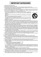
AC adapter section IMPORTANT SAFETY INSTRUCTIONS 1) Read these instructions. 2) Keep these instructions. 3) Heed all warnings. 4) Follow all instructions all servicing to qualified service personnel. Servicing is required when the apparatus has been damaged in any way, such as power-supply cord - JVC BR-DV6000U | User Manual - Page 106
OF JAPAN, LTD. ® is a registered trademark in Japan, the U.S.A., the U.K. and many other countries. © 2003 VICTOR COMPANY OF JAPAN, LIMITED Printed in Thailand LLT0033-001C-H BR-DV6000U DV VIDEO CASSETTE RECORDER
-
 1
1 -
 2
2 -
 3
3 -
 4
4 -
 5
5 -
 6
6 -
 7
7 -
8
-
9
-
10
-
11
-
12
-
13
-
14
-
15
-
16
-
17
-
18
-
19
-
20
-
21
-
22
-
23
-
24
-
25
-
26
-
27
-
28
-
29
-
30
-
31
-
32
-
33
-
34
-
35
-
36
-
37
-
38
-
39
-
40
-
41
-
42
-
43
-
44
-
45
-
46
-
47
-
48
-
49
-
50
-
51
-
52
-
53
-
54
-
55
-
56
-
57
-
58
-
59
-
60
-
61
-
62
-
63
-
64
-
65
-
66
-
67
-
68
-
69
-
70
-
71
-
72
-
73
-
74
-
75
-
76
-
77
-
78
-
79
-
80
-
81
-
82
-
83
-
84
-
85
-
86
-
87
-
88
-
89
-
90
-
91
-
92
-
93
-
94
-
95
-
96
-
97
-
98
-
99
-
100
-
101
-
102
-
103
-
104
-
105
-
106
 |
 |

BR-DV6000U
BR-DV6000U
DV VIDEO CASSETTE RECORDER
INSTRUCTION MANUAL
DV VIDEO CASSETTE RECORDER
BR-DV6000
PROFESSIONAL
MENU
RESET
A.DUB
EJECT
COUNTER
AUDIO
INPUT
SELECT
MONITOR
OUTPUT
REMOTE
LOCAL
CTL
L
MIX
R
CH-1/2
MIX
CH-3/4
DV
LINE
Y/C
(CPN)
TC
UB
REW
STOP
FF
REC
OPERATE
PLAY
PAUSE
DISP
SET
SEARCH+
BLANK
CUE UP
HOLD
PHONES
REC
LEVEL
CH-1/3
CH-2/4
MIC
SEARCH–
Mini
Thank you for purchasing this JVC product.
Before operating this unit, please read the
instructions carefully to unsure the best
possible performance.
LLT0033-001C-H
For Customer Use:
Enter below the Serial No. which is
located on the rear of cabinet. Retain
this information for future reference.
Model No.
BR-DV6000U
Serial No.